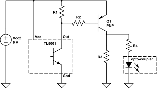
I'm using a PNP transistor with V_CEO= 30V, V_CBO=40V, and V_EBO=10V as a signal inverter for the output from a control IC (TL5001). So, the power source for the TL5001 will be also applied to the emitter terminal which is around 6V, the output voltage from the TL5001 will be applied to the base terminal and the output from the collector terminal will go to the gate driver in my buck converter circuit.
Originally, I was thinking of using the same power source for both my buck converter and TL5001 which is 24V but I used another power source of 6V for TL5001 because of the emitter-base breakdown voltage of the PNP transistor.
My circuit is not working properly so I am not sure I did the right consideration here.
If V_EBO of transistor is 10V, then the voltage which applies to the base terminal should also not exceed 10V?
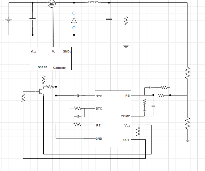
This is my rough circuit schematic. Vcc2 is 6V of power supply.Photocoupler is used for the gate driver. So, PWM voltage will be applied to the base terminal of PNP transistor.
With those breakdown voltage ratings, using 24V which is a input voltage supply for the buck converter will not be able to be used as Vcc2?
https://html.alldatasheet.com/html-pdf/50728/FAIRCHILD/BC516/404/1/BC516.html This is the datasheet for the used PNP transistor.


