4
\$\begingroup\$

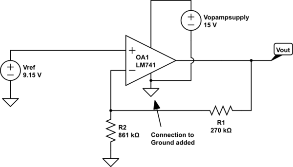
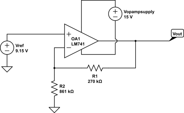
In another question a user posted the following circuit.

schematic

simulate this circuit – Schematic created using CircuitLab

It was explained to the user that the op-amps negative supply rail should be connected to ground, or that a split supply should be used so that the supply was referenced to ground.

Something like the following

schematic

simulate this circuit

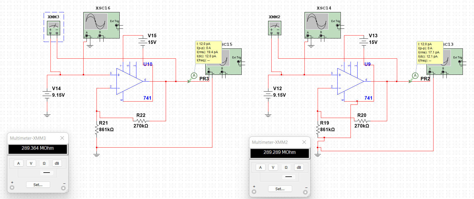
The user questioned why a connection to ground should be added to the negative supply rail for the op-amp. The user commented that both circuits seemed to behave the same. They give different output voltages in CircuitLab, but apparently the user was able to obtains simulations where they both gave an output of 12V.

Here is a copy of an image they posted enter image description here

Since they were unable to detect any difference between the two circuits, they wonder why the ground connection was necessary, and did it make any difference in the circuit behavior.

(I may have made an error somewhere such that the circuits should have given the same voltage, but the need for the ground connection is independent).

Edit: The circuit with the op-amp supply negative rail grounded did not give me 12V in CircuitLab (unless a load resistor is added to the circuit). However, substitution of a TL081 for the LM741 gave me 12.02V.

\$\endgroup\$
5
  • 5
    \$\begingroup\$ Current flows in a loop. If the supply is like that, without ground reference, the op-amp can't drive output current via the feedback circuit to ground, so it can't make inverting input to match non-inverting input. I'll edit this to an answer when you finalize the question. \$\endgroup\$
    – Justme
    Commented May 29, 2022 at 14:24
  • 1
    \$\begingroup\$ The reason they're seeing no apparent difference in behaviour is that they're measuring the current flowing into the oscilloscope and incorrectly thinking it should be much larger. \$\endgroup\$
    – Finbarr
    Commented May 29, 2022 at 14:43
  • \$\begingroup\$ @Finbarr but they are getting 12V with both circuits. I do not get 12V with either, nor are my results the same with the 2 circuits. I think they may have changed the resistor values in the image without re-running the DC simulation, but I don't know. \$\endgroup\$ Commented May 29, 2022 at 14:47
  • 1
    \$\begingroup\$ @MathKeepsMeBusy But you haven't got a multimeter set to Ohms connected up, presumably in some misguided attempt to measure the output impedance. And I don't see where the original questions said they were getting 12V anyway but that may now be hidden. \$\endgroup\$
    – Finbarr
    Commented May 29, 2022 at 14:51
  • \$\begingroup\$ @Justme has the key...current paths coming in/out of the opamp's output pin are sourced from either +ve supply pin or -ve supply pin. I'm not considering the case when you try to drag output pin outside the +ve or -ve supply rails. \$\endgroup\$
    – glen_geek
    Commented May 29, 2022 at 14:53

3 Answers 3

11
\$\begingroup\$

Why does does the power supply in my op-amp circuit need to be connected to ground?

There are two ways to approach this problem. One way is to look internally into the op-amp and discover what happens when the ground is present or absent.

Another approach is to treat the op-amp as a black box. That is, we completely ignore what is inside the op-amp, and try to determine the behavior from the outside.

In this answer, we will use the second approach. We will treat the op-amp as a black box.

We consider the case where the connection to ground is missing.

  1. The algebraic sum of all the currents into and out of the op-amp must total zero, otherwise charge would be building up inside the op-amp.

  2. Since the op-amp power supply has only two terminals, (it is not split!) the current from the power supply into the op-amp must equal the current out of the op-amp back into the power supply.

  3. Since the power rails into the op-amp have equal current, it must be the case that the total current into the op-amp's signal inputs must equal the current out of the op-amp's output

  4. When an op-amp is operated in its "normal" linear range, the current into (or out of) the inputs is very small. Sometimes it is treated as 0. Also, when an op-amp is operated in its linear range, the voltage difference between the non-inverting input pin and the inverting input pin will be "small".

  5. From the above, if the op-amp is operating in its linear range, the current at its output must also be very small -- almost 0.

  6. If the output current of a circuit is near 0, but its voltage is not, then if any load whatsoever is added to the output, it will generally have a great effect upon the output voltage.

  7. Thus, the output voltage of the op-amp, in this configuration, will vary significantly depending upon load, rather than being controlled by the feedback network.

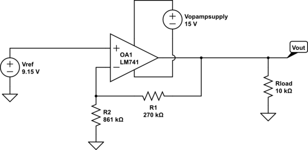
To demonstrate this:
schematic

simulate this circuit – Schematic created using CircuitLab

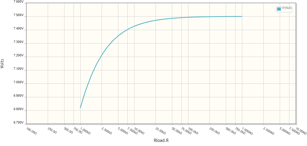
Here is a DC sweep showing how the output voltage changes from 6.8 V to 7.5 V as the load changes from 1 k\$\Omega\$ to 1 M\$\Omega\$.
enter image description here

[Note: I do not trust the CircuitLab model to accurately reflect how the circuit will actually behave when the op-amp power supply is "floating" relative to ground. I merely wish to illustrate how, once the output current is severely limited, the output voltage becomes dependent upon the load, and parenthetically on the absolute magnitudes of the resistors in the feedback network, and not merely upon their ratio.]

We can also see, by looking at the op-amp's inverting input pin, that the op-amp is not operating in it's linear region. If it were, the op-amp's inverting input pin would be close to the voltage of the non-inverting pin (i.e. 9.15V). Instead, it is 3 V or more away.

This explains why the output is seen to vary between 6.8 V and 7.5 V rather than being near the 12 V hoped for by the designer.
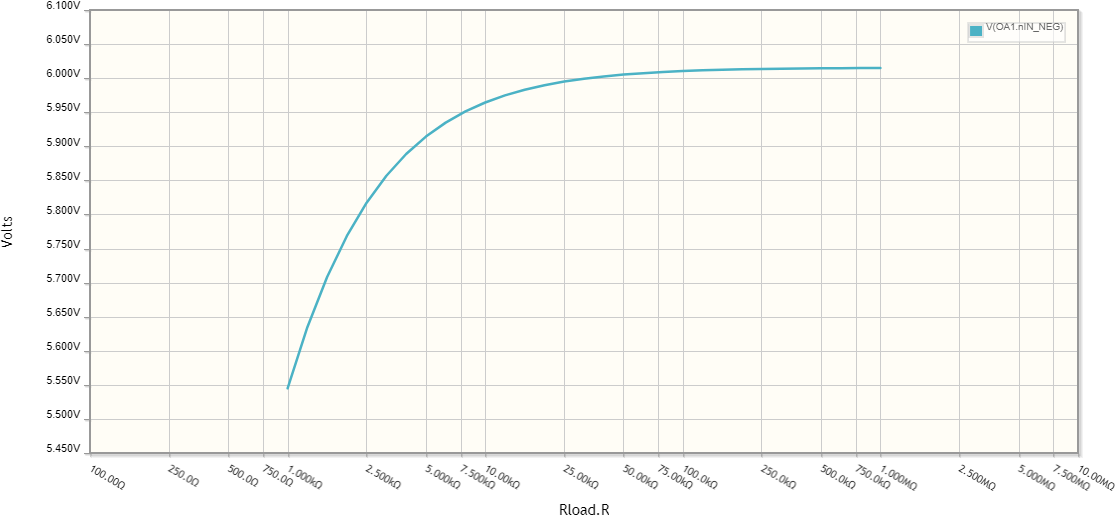
enter image description here

In contrast, when the op-amp supply's negative rail is grounded, the voltage changes little when the load is varied. Although the curve in the following graph looks significant, the labels marking the grid lines show that as the load varies from 1 k\$\Omega\$ to 1 M\$\Omega\$, the output voltage remains 12.04 V within +/- 0.005 V.
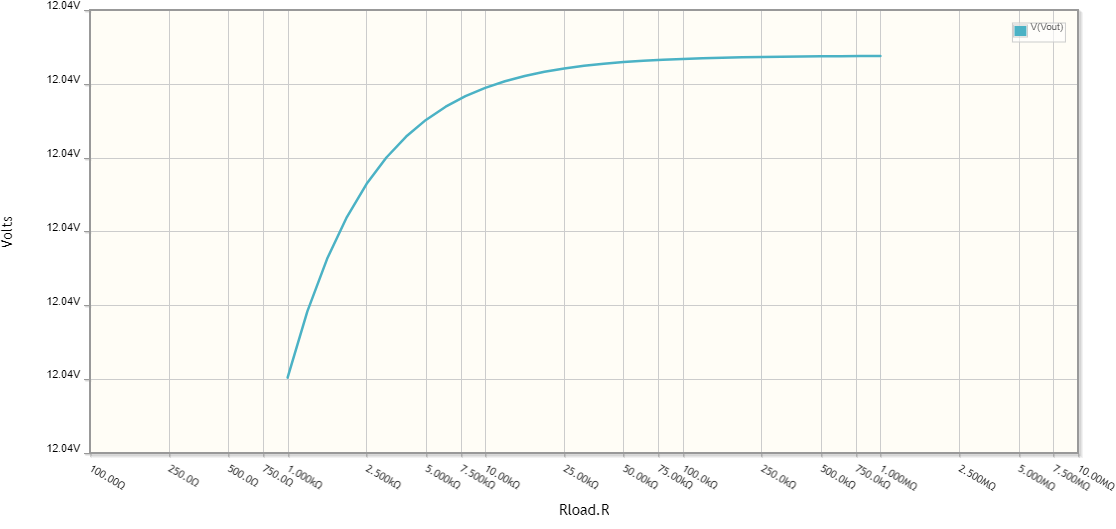
enter image description here

Incidentally, this result corresponds to the 12 V (approximately) expected by the user.
\$\endgroup\$
2
  • \$\begingroup\$ Hardly anyone else here might value this: this answer would be a lot clearer to me if you added something at the end showing how grounding the power supply changes things. \$\endgroup\$ Commented May 30, 2022 at 1:08
  • 2
    \$\begingroup\$ I have added a graph of how the output voltage changes with load when the negative supply rail is grounded. Pay careful attention to the labels on the Y-axis, because although the output voltage appears to vary significantly, the variation is actually less than +/- 0.005 V. (perhaps much less). \$\endgroup\$ Commented May 30, 2022 at 1:28
3
\$\begingroup\$

Simply put, the Vinputs must be within the common mode range of the datasheet. In order to establish 0V for inputs, the supply must also be referenced to 0V.

Since 9.15V is the input on Vin+=Vin-. The Vcm inputs are satisfied but allow a few volts to each rail or read specifics of datasheet.

\$\endgroup\$
1
  • \$\begingroup\$ "In order to establish 0V for inputs, the supply must also be referenced to 0V." - why? Why can't it just float up and down wherever it likes within the common mode range? \$\endgroup\$ Commented May 30, 2022 at 1:46
0
\$\begingroup\$

Circuit diagrams are an approximation of reality. In reality, any floating circuit is going to behave as an antenna. Usually, this is undesirable. If you want to model this effect, attach an in-line inductor followed by a capacitor between all elements of the floating loop, and connected to all other nodes in the circuit, as well as ground, whatever housing is used for the device, any nearby microwave ovens, your Wi-Fi routed, and the 60Hz mains current probably running through nearby walls.

This reminds me of university when people would wonder why an RC circuit with a 1Ω and a 1mF capacitor didn't work, but when replaced with 1kΩ + 1uF components, it did.

\$\endgroup\$

Your Answer

By clicking “Post Your Answer”, you agree to our terms of service and acknowledge you have read our privacy policy.

Not the answer you're looking for? Browse other questions tagged or ask your own question.