0
\$\begingroup\$

I am learning electronics and needed a negative rail. I have two transformers that have the same rated input/output voltages but different power ratings and manufactured by different companies.

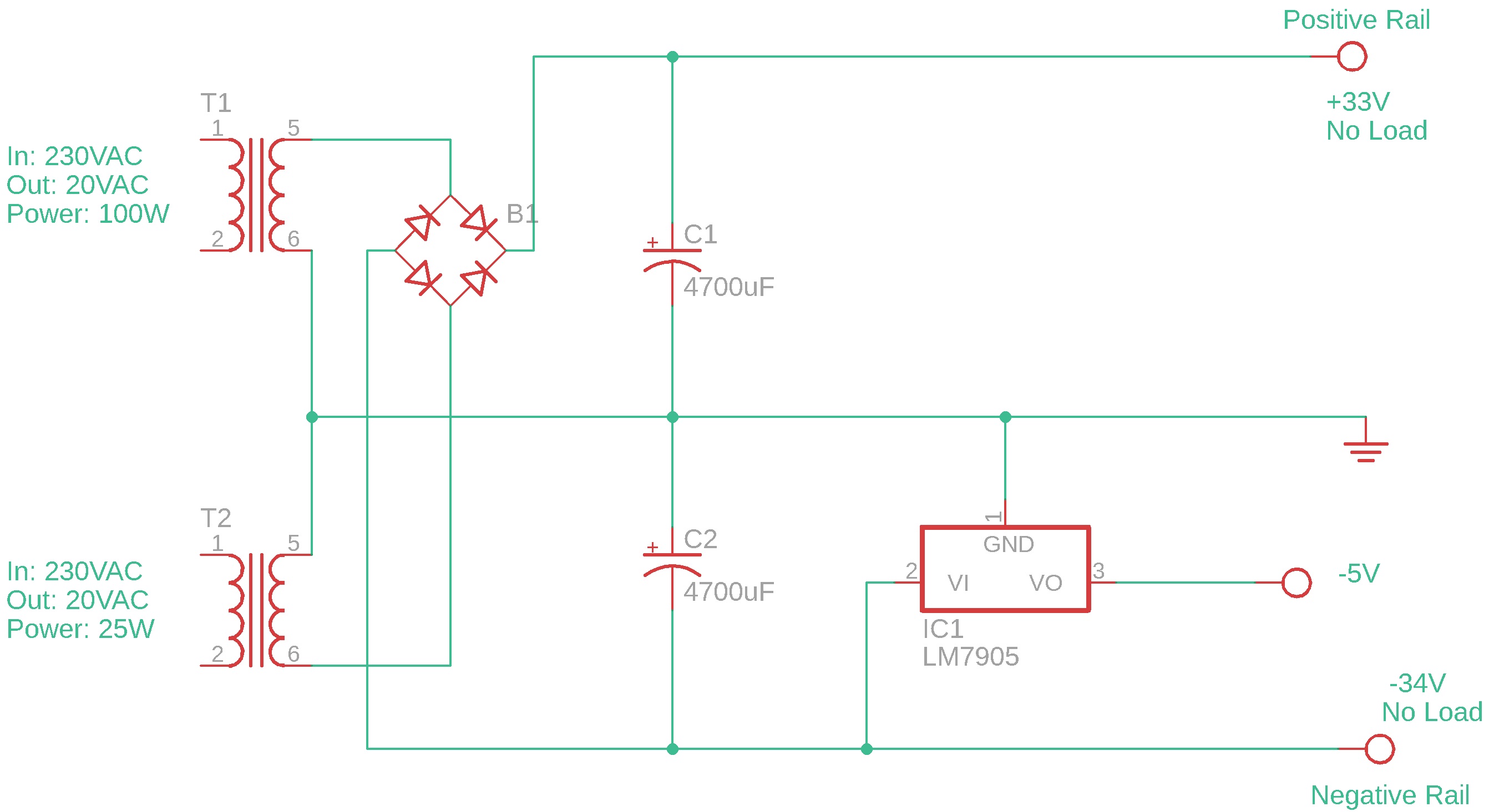
Transformer 1: Input 230VAC, Output: 20VAC, Power Rating: 100W.

Transformer 2: Input 230VAC, Output: 20VAC, Power Rating: 25W.

The higher powered transformer (100W) I used for the positive rail and the lower powered (25W) transformer I used for the negative rail.

Everything seemed OK under no load but then I added an LM7905 to the negative rail and found that the regulator could not regulate the voltage. The voltage output of the LM7905 slowly goes up (i.e. progressively gets less negative).

If I just use the 100W transformer, center tapped (+/-16V no load), for the same circuit the regulator regulates the voltage no problem.

By the way, I was not going to exceed 1.25A from the negative rail to ground or exceed 5A from the positive rail to ground.

Please see schematic below.

So I actually have three questions:

  1. Is it OK to put in series (secondary coils) two transformers with the same rated input/output but different rated power? Why or why not?

  2. Why is the regulator unable to regulate the voltage properly in this scenerio?

enter image description here

\$\endgroup\$
11
  • 4
    \$\begingroup\$ The circuit you've drawn here does not use one transformer for the positive rail and the other for the negative rail. It uses both transformers for both rails, and as such your effective output current from both rails is limited by the smaller transformer. \$\endgroup\$
    – brhans
    Commented May 31, 2022 at 12:44
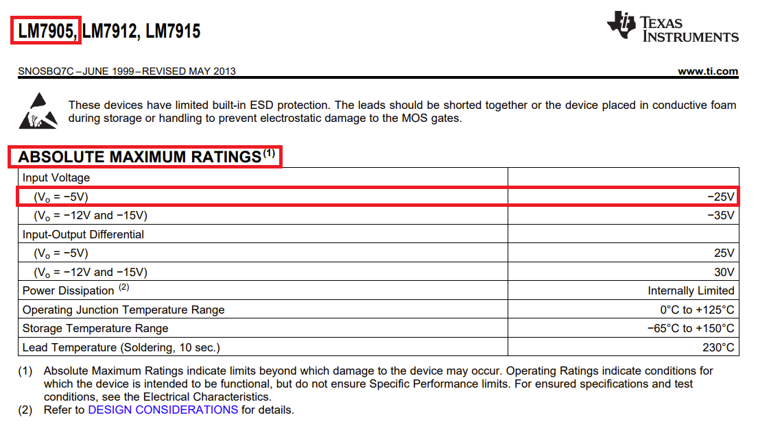
  • \$\begingroup\$ You're also exceeding the absolute maximum Input Voltage rating of your 7905. According to this TI datasheet, the maximum input for a 7905 is -25V. \$\endgroup\$
    – brhans
    Commented May 31, 2022 at 12:47
  • 1
    \$\begingroup\$ You're also probably exceeding the power/thermal rating of the 7905. With a 30 V differential in to out, it needs only 60 mA output current to be dissipating about 2 watts, which is the absolute maximum you can expect a TO-220 package to manage without a heatsink \$\endgroup\$
    – Neil_UK
    Commented May 31, 2022 at 12:51
  • \$\begingroup\$ @brhans, about the circuit limit, yes I was a little bit curious about that. So the power limit is 25W as shown? OK. If I used two bridge rectifiers would that me to essentially isolate the effective currents of each transformer? \$\endgroup\$
    – Pat
    Commented May 31, 2022 at 12:51
  • \$\begingroup\$ Yes, if you used 2 bridge rectifiers - one for each transformer - then you could use one for the positive rail and the other for the negative. And in that case you would not connect the transformers together, you would connect an output from the rectifiers. \$\endgroup\$
    – brhans
    Commented May 31, 2022 at 12:52

1 Answer 1

1
\$\begingroup\$

Be very careful here.

You have used an LM7905 for the negative rail but, according to the TI data sheet, the maximum input voltage is limited to -25 volts: -

enter image description here

Your schematic appears to indicate that your input supply is -34 volts and this may increase if the AC mains input rose to grid limits.

I'm not saying that this is your major problem but it certainly looks like a show-stopper for the design. Consider other regulator options. Maybe put a voltage reducing resistor in series with the input to the LM7905 to drop several volts to ensure the -25 volt limit is far from being exceeded.

However....

By the way, I was not going to exceed 1.25A from the negative rail to ground

This is also pretty much not going to be a good move. Even with the input to the 7805 limited to -25 volts, the power dissipation will be 1.25 amps × 20 volts = 25 watts and it'll thermally shut-down. Maybe this is what you are seeing?

Use a switching regulator for this part and use separate bridge rectifiers for both positive and negative rails.

\$\endgroup\$
5
  • \$\begingroup\$ @ AKA_Andy. OK so it is a 7905. The Onsemi datasheet says max. V at -35V. I am seeing this behavior with no load on the regulator. I have tried two and they are brand new. I have not loaded the reglator yet. \$\endgroup\$
    – Pat
    Commented May 31, 2022 at 13:15
  • \$\begingroup\$ @Pat the ON semi LM7905 is no longer manufactured so why choose it? Nevertheless you won't get 1.25 amps from it when the input supply is so large. Even so, -35 volts will be exceeded if the nominal AC mains grid supply input rises by 3.3% so it's still not a good choice. \$\endgroup\$
    – Andy aka
    Commented May 31, 2022 at 13:26
  • \$\begingroup\$ @AKA_Andy I am a bit confused as I have successfully run 78XX on a +33 rail so I figured the behavior of the 79XX would be similar since the datasheets seem basically the same except one for positive rail and one for negative rail. But OK, let me check the thermal properties. Also, I will adjust the circuit as brhans suggests and add another bridge rectifier. I wanted to isolate the currents anyways and was unclear how, but I see now. \$\endgroup\$
    – Pat
    Commented May 31, 2022 at 13:27
  • \$\begingroup\$ @AKA_Andy, sorry if my post was a bit confusing. I never actually indended to load the 7905 at 1.25A. I would keep the draw to 1A or less as the datasheet specifies. I was talking about the transfomer load not the 7905 load. Also, I am just learning so I don't really care if the part is in production or not but I see how you are thinking about this in terms of the mains variation and it is good for me to be thinking that way. Thanks. I guess I am running my LM78XX and LM79XX perhaps too close to max. I'll have a second look. \$\endgroup\$
    – Pat
    Commented May 31, 2022 at 13:34
  • \$\begingroup\$ @Pat, your 7905 has two limits: maximum current and maximum power dissipation. You can't assume you can go right to the current limit, you must check that you're not violating the power limit. Especially with 25 V drop, you will find the current limit is irrelevant and the part shuts down due to overheating long before you reach 1 A. It could very well shut down at around 100 mA or lower if you don't use a heat sink. \$\endgroup\$
    – The Photon
    Commented May 31, 2022 at 15:48

Your Answer

By clicking “Post Your Answer”, you agree to our terms of service and acknowledge you have read our privacy policy.

Not the answer you're looking for? Browse other questions tagged or ask your own question.