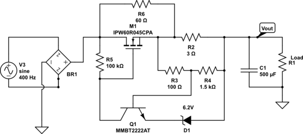
I couldn't find details of this circuit configuration in an internet search. Most online results are about P-MOSFET in high side path or N-channel MOSFET with charge-pump/IC based driver.

simulate this circuit – Schematic created using CircuitLab
I understand the high level working of above circuit. It is part of an inrush limiter circuit and would hold the current through M1 constant during C1 charging.
- R6 provides the initial path to build up output voltage.
- Due to voltage drop across R2, Q1 Vbe crosses the threshold and starts conducting.
- This increases the Vgs of M1 and it starts conducting, bypassing R6.
- Current through R2 is maintained constant by the feedback effect on Vgs
Why is it not very popular? Any drawbacks for this circuit? What is the purpose of R5?
I could find a similar circuit in another SE answer- but it was with P-channel MOS.
