1
\$\begingroup\$

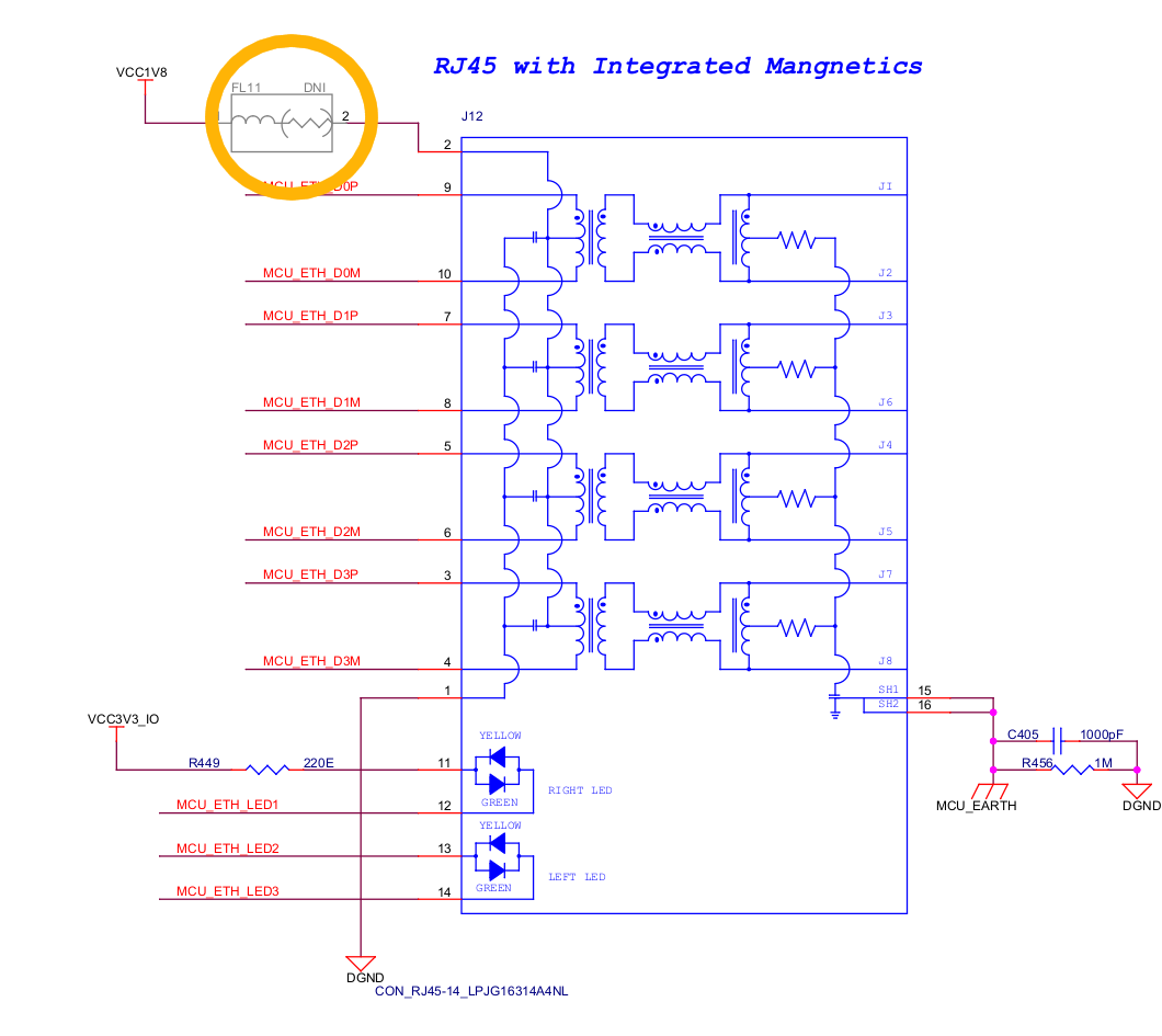
The symbol I'm looking for is the one inside the circle of the schematic. I thought it could be some special kind of fuse, but I haven't seen anything like this before, nor been able to find anything similar myself. Regarding this schematic, I would also like to ask a few questions:

enter image description here

  • What's the purpose of connecting Vcc (1.8V) to the RJ-45 connector? Someone said that it could be because the output of the PHY transceiver was open drain. If that's the case, would that mean that if my transceiver is fed with 3.3V, I should supply the same voltage to the Ethernet connector?
  • About the RC filter dividing those 2 grounds. As far as I knew, the higher the frequency of the transmission, the better to be those 2 grounds directly coupled (I know that the higher the 'f', the lower the impedance will be). Anyway, I thought that that small impedance could be enough reason for the cable to emit EMI. Why is it done this way? Does the shielding of the connector provide enough protection to avoid this?
\$\endgroup\$
3
  • 1
    \$\begingroup\$ For point 2, are you asking why those two grounds are not coupled? If so, its because one of the big advantages of ethernet is that its isolated - Ethernet networks can stretch for long distances and connect all different kinds of equipment, which may all have different grounds. If ethernet wasn't isolated, large and potentially dangerous currents would flow through the wires, causing all sorts of issues and probably breaking devices. \$\endgroup\$
    – BeB00
    Commented Jun 23, 2022 at 7:48
  • \$\begingroup\$ Thank you for your answer @BeB00, I thought that being a cable carrying high frequencies could be somehow a problem in terms of emitting radiation. But I guess a good shielding of the cable can be enough. Appreciate it :) \$\endgroup\$
    – Kike Rueda
    Commented Jun 23, 2022 at 8:17
  • \$\begingroup\$ Not all cables are shielded, like UTP. \$\endgroup\$
    – Justme
    Commented Jun 23, 2022 at 8:47

2 Answers 2

1
\$\begingroup\$
  1. FL11 is likely just a ferrite bead. But as it is greyed out and reads "DNI" it means it is not populated in the circuit, so 1V8 would not be connected to connector. The diagram is only an example how it might be used, but it must be connected how the PHY requires the connections. Some PHYs allow or require it to be left unconnected, some PHYs require it to be connected in certain way, and this connector may not even be comptible with certain PHYs. Some PHYs allow the mode of operation to be changed in hardware or software so it is the PHY datasheet that says how to connect it.

  2. Yes it might be bias current for an pull to ground type output. But just because your PHY is fed with 3.3V supply, it does not mean the analog front end inside the PHY chip operates at 3.3V, and more likely the chip core operates at lower 1V8, which may be generated internally or with external regulator. 3V3 might just burn the chip or at minimum cause too high voltages on wire if it is not intended to connect it to 3V3.

  3. Grounds are difficult. Ethernet is an isolated interface anyway. The connector metal shield should be connected to device metal chassis - if you have one. How you intend to connect the metal chassis to your PCB digital ground plane, if at all, is completly another thing. Here, the resistor keeps the metal chassis and PCB ground at same potential by weakly leaking charges, and the capacitor provides a stable low impedance ground reference for shunting high frequency RF signals. Please note that there already is a capacitor inside the magjack, connecting the cable center taps to connector metal shell. Another separate thing is if the device metal chassis or PCB digital grounds are connected to earth ground or not, but a shielded Ethernet cable connects the cable shield to connector metal shell, which is something you just need to be aware of.

\$\endgroup\$
1
  • \$\begingroup\$ Thank you very much for your info, it is actually quite complete. Last time I worked in electronics was for my degree thesis, doing an small simple PCB. Now I'm hired as the only hardware engineer in the company to create a PCB which has an SoM and few ethernet, PCIe... connections, which are way more complicated than what I did back then. I kinda feel like a 'sus' in here, but I'm trying my best and I'm learning quite a lot. So, again, thank you for your response, it's been really helpful :) \$\endgroup\$
    – Kike Rueda
    Commented Jun 23, 2022 at 9:25
2
\$\begingroup\$

FL11 is most likely a ferrite chip bead. VDD to the transformer center tap shouldn't be higher than the VDD of your ethernet PHY because even if it has open drain output, there are probably diodes from output to its VDD, which could form a short circuit and lead to damage if conducting with unlimited current. When using a push-pull-output PHY, the bead indeed should not be populated because connecting a supply voltage to the transformer center tap would half the signal amplitude.

Isolating the connector shield and chassis from circuit ground is one key property of Ethernet.

Sometimes a large resistor is places between them though, to prevent the circuit ground from floating away, if it is not already anchored to ~Earth potential by other means. The small capacitor provides a return path for any common mode noise that couples through the isolation transformers due to their parasitic capacitance.

\$\endgroup\$
3
  • \$\begingroup\$ Thanks for the answer tobalt. And would you recommend to connect Vdd to the transformer center? Here in this schematic they have a Do Not Insert comment on the ferrite bead, disconnecting the Vdd from the connector. Some other connectors don't even have the pin connector for the supply like this one. Under which situation would you recommend to use it? It's a good practice to have Vdd connected, or it's just for certain application/situations? \$\endgroup\$
    – Kike Rueda
    Commented Jun 23, 2022 at 8:20
  • \$\begingroup\$ @KikeRueda I suppose the option to supply the transformer center tap is there to use open drain PHYs as you suggested. But if you have PHYs with push-pull output, then the transformer should not be connected to VDD. \$\endgroup\$
    – tobalt
    Commented Jun 23, 2022 at 8:22
  • 1
    \$\begingroup\$ That diagram is an example how to use the connector. How to actually connect it and to which voltage depends on the PHY, not the connector. There might be PHYs that require different kind of connections and this connector may not be compatible with the PHY depending on PHY requirements. See my aswer for more info. \$\endgroup\$
    – Justme
    Commented Jun 23, 2022 at 8:30

Your Answer

By clicking “Post Your Answer”, you agree to our terms of service and acknowledge you have read our privacy policy.

Not the answer you're looking for? Browse other questions tagged or ask your own question.