0
\$\begingroup\$

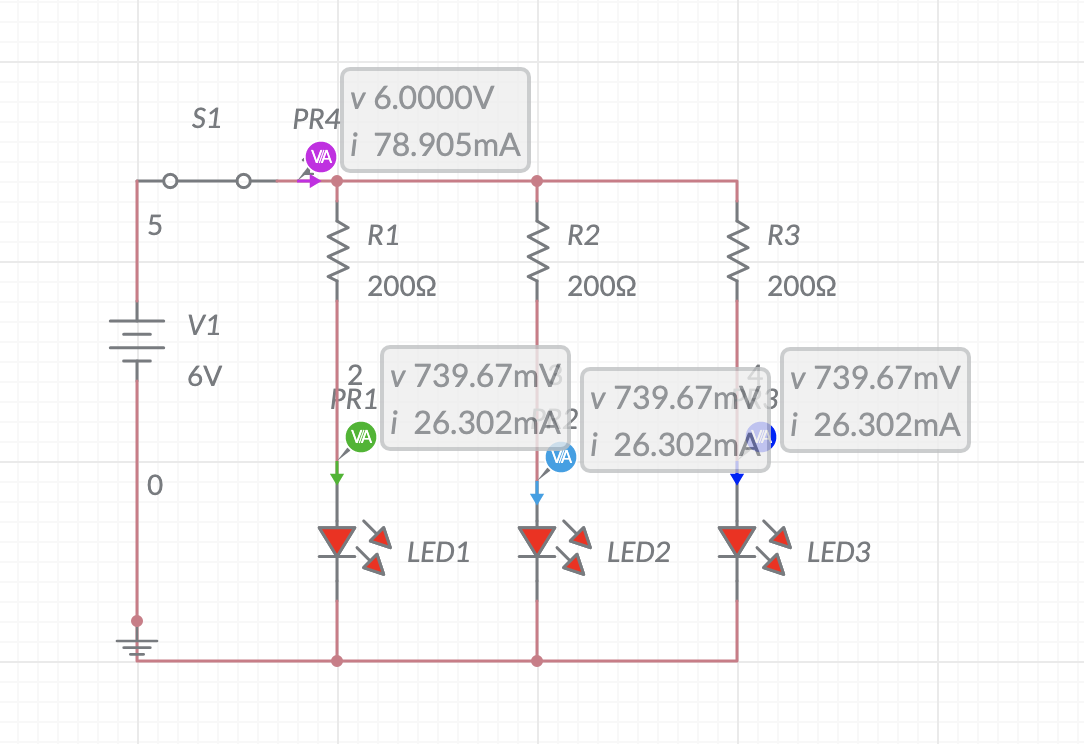
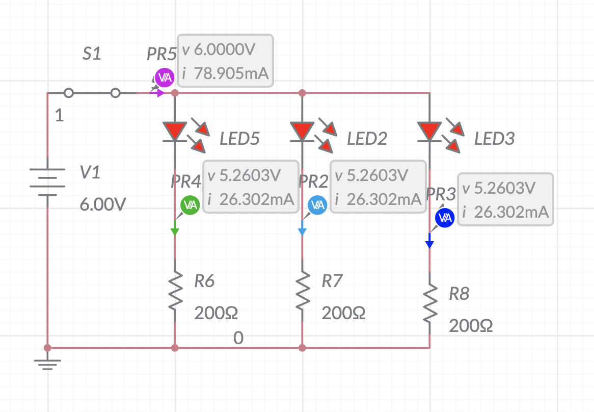
I'm a beginner. These two circuits are the same, except one has the resistors placed above and the other with the resistors placed below.

They both have the same current going through, except the voltage. One has 5.2603V and the other 739.67 mV.

  1. Why do they have different voltages? I still don't really understand how electricity flows from the power source and how this affects the voltage basically.
  2. Does the difference in said voltages matter in real life applications? For example, I built out these two circuits on my breadboard, and they both work just fine, so I'm wondering if I'm missing something.

enter image description here

enter image description here

\$\endgroup\$
2
  • \$\begingroup\$ Replace a diode with a resistor (of different value) and you'll see the same effect: current remains the same regardless of which resistor is on top, but the voltage in the middle changes. \$\endgroup\$
    – td127
    Commented Jun 25, 2022 at 17:52
  • \$\begingroup\$ Nobody makes an LED that has a voltage as low as 0.74V. \$\endgroup\$
    – Audioguru
    Commented Jun 25, 2022 at 18:55

5 Answers 5

2
\$\begingroup\$

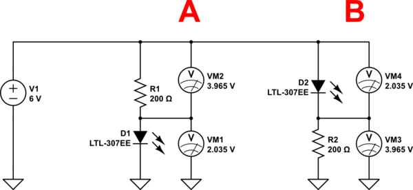
As others have mentioned, your voltages are more typical of a small silicon diode than an LED. Circuitlab simulation below:

schematic

simulate this circuit – Schematic created using CircuitLab

The LTL-307EE is a typical modern red LED. Other colors may be more like 3V, IR LEDs will be 1.2V or so.

Note that VM1 + VM2 = V1 = 6V, and VM4 + VM3 = V1 = 6V so the circuit does not really care which order the series connected parts are connected in.

As to real-world differences- imagine you have a grounded chassis and wires running to the LED.

If you short either lead to the chassis in configuration A nothing really bad will happen, at worst you short the LED out (so it doesn't light up) and R1 gets a bit warmer.

In configuration B the LED will most likely be destroyed if the cathode lead is grounded and the power supply will be shorted out if the anode lead is grounded.

\$\endgroup\$
2
\$\begingroup\$

Remember, all voltage is measured between TWO points.

It is impossible to measure the voltage at one point in the circuit so if the two points that the voltage is being measured across is not explicit then that means it is implicitly using some other point in the circuit to measure against which is whatever you have labelled as 0V/GND for your circuit.

If you agree that the voltage across the LEDs in both circuits are the same, and you agree that the voltage across the resistors in both circuits are the same then you must also agree that the voltage measured between the ONE point indicated in your schematics and ground must be different (if the voltage across LED and resistors are not equal).

If I am 5 feet tall and you are 6 feet tall these heights will not change as long as you measure between head and feet. But if I stand on your head or you stand on my head, the height between the ground and the head of the person on the bottom will obviously be different depending on who is on the bottom.

\$\endgroup\$
1
\$\begingroup\$
  1. When circuit elements are wired in series it doesn't matter which order they're in. The same current will flow in either case and your simulation shows that.
  2. LEDs don't behave like resistors. They require enough voltage to "crack them open" (start to turn on) and then the voltage drop across them changes relatively little as the current through them increases. See if my article What is an LED helps your understanding.
  3. Your circuits have a 6 V supply and there is 26 mA flowing through each branch. The resistors are easy: the voltage drop is given by \$ V = IR = 0.026 \times 200 = 5.2 \,\text V \$. That leaves 6 - 5.2 = 0.8 V for the LED. (The simulator voltages are measured relative to the ground symbol so that explains why the readings differ.)

The only thing I see wrong is that the voltage drop across the LEDs is too low. The 700 mV drop is what you would get from a regular diode, not an LED.

enter image description here

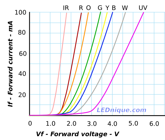
Figure 1. Typical IV curves for various colours of LEDs. Image source: LEDnique.

From Figure 1 you can work out the typical small LED forward voltage which starts at about 1.3 V for an infrared LED and increases for red (1.8 V) through to UV (3.7 V) hence my suspicion about the 740 mV readings in your diagrams.

\$\endgroup\$
1
\$\begingroup\$

The only difference is the order of the resistors and LEDs.

Look at just one of the resistor/LED pairs. The supply voltage, 6.0 V, causes a current to flow through them. The current is determined by the resistance of the resistor and the voltage drop of the LED.

In each case 26.302 mA flows through the resistor and LED. This current will cause a voltage drop across the resistor according to Ohm's Law $$ V = {I}\cdot{R}$$ So $$ V = {0.0263~A}\cdot{200~\Omega} = 5.26~V $$ and the voltage across the LED is $$ 6.0~V - 5.26~V = 0.74~V $$

In one schematic the LEDs are on top, so you are measuring the voltage across the resistor, 5.25 V, in the other the the resistor is on top so you are measuring the voltage across the LED, 0.74 V. In a series circuit it doesn't really matter which order the components are in, it will work either way.

The voltage drop across an LED, called the forward voltage is determined by the semiconductor materials it is made from. Different color LEDs have different forward voltages. Infrared ones have the lowest, down to maybe 1.2 V, ultraviolets can be over 4.5 V. The voltage also increases with increasing current.
The LEDs in your circuits are only showing 0.74 V @ 26 mA, which is probably because they are not modeled properly in whatever simulator was used.

\$\endgroup\$
0
\$\begingroup\$

In the top circuit you are measuring the voltage across the resistors which is equal to 5.2603 V. In the bottom circuit you are measuring the voltage across the LEDs which is 739.67 mV. If you add those two voltages together, the total equals just about 6 V which is the supply voltage.

\$\endgroup\$

Your Answer

By clicking “Post Your Answer”, you agree to our terms of service and acknowledge you have read our privacy policy.

Not the answer you're looking for? Browse other questions tagged or ask your own question.