1
\$\begingroup\$

I would like to create charts. Voltage as a function of time. I want to do this to test models of different battery manufacturers. I want to see which battery contains the most Ah. I have done some reading: I need to discharge slowly so I don't have thermal effects. I need a constant discharge current so I can rely on the data. I know by now, I need a current sink. This current sink is what this question is about. Have I done everything right here? What can I improve?

1.) Where do I have to place the battery?

2.) Is the following correct?

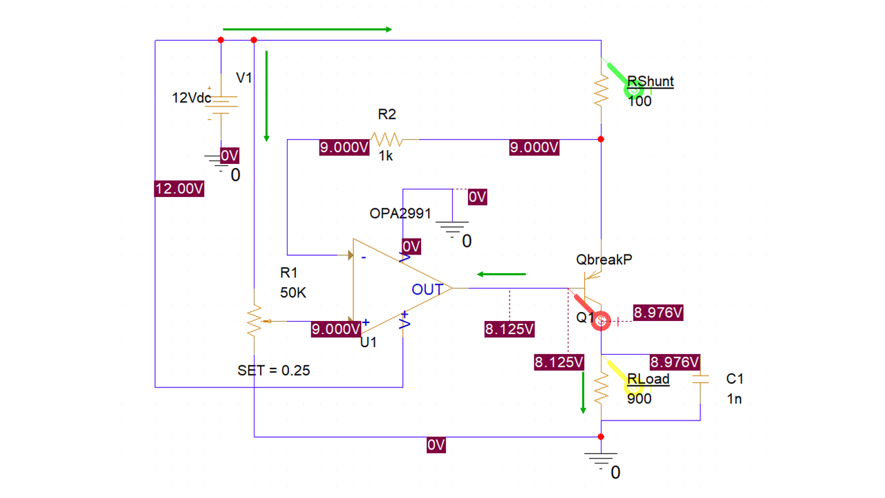
The current sink exploits the fact that the opamp wants to reach the same voltage on both inputs. Therefore, it controls its output accordingly. Since there is only 9V on the plus input, but 12V on the minus input, there is a negative current (from the pnp transistor towards the OPV) and a positive voltage which switches the transistor through. A constant current flows through \$R_{Load}\$. Let me get this straight – \$R_{Load}\$ is the resistor to measure, isn't it? \$R_{shunt}\$ serves to control the current into the Emitter.

PS: I use PSpice For TI2022. Therefore, I have only parts from Texas Instruments and PSpice available. Please keep this in mind when you suggest a part.

enter image description here

enter image description here

\$\endgroup\$
1
  • 2
    \$\begingroup\$ Should work, but you are making it a little bit harder on yourself by using high side current sense. Unless you need battery negative to be connected to GND, a low side sink is favorable. \$\endgroup\$
    – winny
    Commented Jul 8, 2022 at 18:33

2 Answers 2

2
\$\begingroup\$

I made this current sink to discharge a 9 V battery. Is this okay?

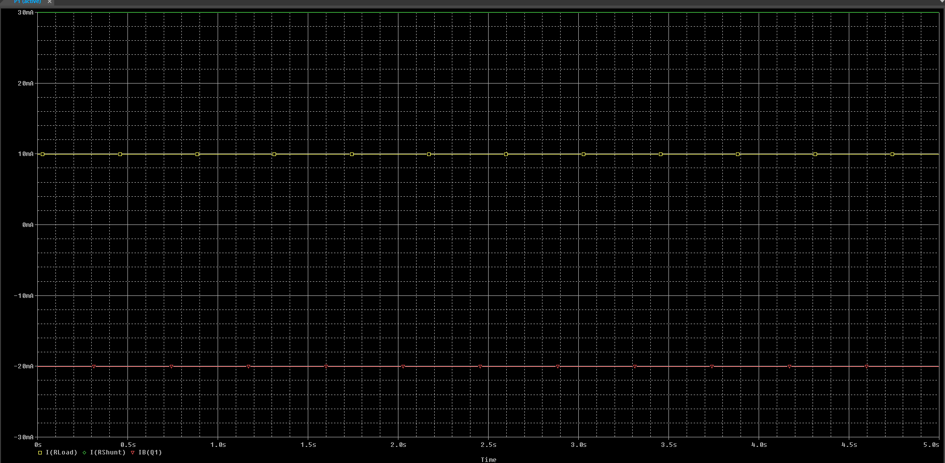
Your circuit appears to do what you want i.e. you appear to have 30 mA flowing through \$R_{SHUNT}\$ but, that current is flowing also into the OPA2991 output and that is totally undesirable.

The main problem is that \$R_{LOAD}\$ is far too high. Think about it; if 30 mA were flowing through it then, because it is 900 Ω in value, there would have to be 27 volts across it.

So, \$R_{LOAD}\$ has to be a lot smaller such that with (say) 6 volts across it, 30 mA can flow. This means \$R_{LOAD}\$ has to be more like 200 Ω.

It can be less of course but that then means the BJT (Q1) might dissipate too much heat. If it were 200 Ω the BJT would dissipate only 90 mW and that's probably OK even for most SMD parts. If \$R_{LOAD}\$ were a short circuit, then the BJT would dissipate 270 mW. If that is OK then make \$R_{LOAD}\$ a short circuit; it doesn't play a role in controlling the current any way.

Another problem is that the voltage you set on the non-inverting input defines the current flow and, if the battery you are discharging lowers in voltage (as expected) then, the value of the discharge current also lowers. To avoid this you need a fixed voltage reference relative to the positive rail. Maybe use a precision shunt reference tied to the positive rail.

The op-amp seems a good choice and the basic circuit choice is good. It's just values and subtleties that are problematic.

Where do I have to place the battery?

Electrically; exactly where you show it to be.

Is the following correct?

It's basically correct but, as I have indicated there are some subtleties.

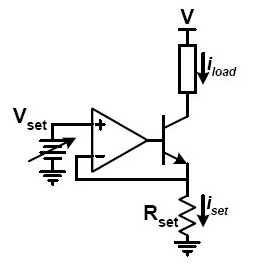
Alternatively, why go the complication of a high-side current source circuit when you can save problems with a low-side current sink circuit like this: -

enter image description here

There are far more op-amps that will "hug" the negative rail with their inputs than the positive rail and, it's a little easier to see what is going on. Image from this answer. Here's another answer where I offer a few alternatives.

\$\endgroup\$
2
\$\begingroup\$

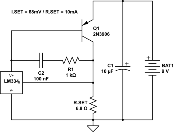
I would use an LM334 and a PNP transistor. The circuit will operate down to about 1.8V:

schematic

simulate this circuit – Schematic created using CircuitLab

For a bit more commentary on the basics of this idea, see this article.

Q1 takes the thermal dissipation away from LM334, and ensures minimal thermal drift. Recall that LM334's thermal voltage varies by 0.227mV per Kelvin.

The battery's internal impedance rises as the battery discharges, and C1 is necessary to stabilize the AC impedance, so that the regulator can operate in the same stability conditions throughout the discharge.

R1 and C2 are optional for stability. The battery is a constant voltage source. The step response and settling time of this circuit are only of secondary importance.

To tweak the values, connect a function generator set for 50 Ohm load, square wave output, 1kHz, via a 100uF DC blocking capacitor to the battery. This will add a "saw" waveform on top of the battery voltage. Add a current-to-voltage amplifier in series with the battery. This lets you adjust the compensation components for best current settling after each disturbance.

\$\endgroup\$

Your Answer

By clicking “Post Your Answer”, you agree to our terms of service and acknowledge you have read our privacy policy.

Not the answer you're looking for? Browse other questions tagged or ask your own question.