1
\$\begingroup\$

I am wondering if I could modify a MT3608 boost module by winding a custom inductor / transformer for it, to generate a kV range voltage (at sub mA current).

I'm thinking of replacing the 22uH inductor with a transformer with a similar primary inductance and turns ratio of about 10:1 for a step up voltage of a few hundred volts. Page 14 of https://www.mouser.co.uk/datasheet/2/609/lt1304-1504180.pdf (LT1304) shows the kind of scheme I want to attempt, the top circuit with the Cockcroft-Walton multiplier on the output (my application is for a photomultiplier tube for a scintillation counter). I doubt I can legally copy that image here but essentially its just a standard boost converter with a flyback transformer instead of a inductor.

I only need a few hundred microamps output.

The MT3608 runs at around 1.3MHz which is higher than I have experience with.

Would trying some ferrite rod material be a decent start? Or should I be looking at a bobbin, very small E core, etc. I've got plenty of old magnetics around here, but most of them are much larger than what I imagine I would need - the smallest probably half an inch to an inch cubed. Would it be a problem to use a much larger core than is needed? I realise I need an air gap, but since I am not trying to get high power through a minimally sized ferrite, can I just use a bit of ferrite rod for instance?

\$\endgroup\$
9
  • 1
    \$\begingroup\$ Getting low interwinding capacitance for SRF >> 1.3MHz will be a learning experience ! on the secondary. \$\endgroup\$
    – D.A.S.
    Commented Jul 14, 2022 at 12:43
  • \$\begingroup\$ Why not simply step up line voltage and rectify then filter and regulate \$\endgroup\$
    – D.A.S.
    Commented Jul 14, 2022 at 12:48
  • \$\begingroup\$ Its for a battery application - I need around 1.5kV at about 200uA from a battery \$\endgroup\$
    – Pete
    Commented Jul 14, 2022 at 12:57
  • 2
    \$\begingroup\$ 1.3 MHz sounds impractial for me \$\endgroup\$
    – Jens
    Commented Jul 14, 2022 at 13:37
  • 1
    \$\begingroup\$ CHoose a simple audio power oscillator and step up transformer x30 to x100 and compute impedances then vary the attenuation of audio for regulation with feedback and bufferfor current gain \$\endgroup\$
    – D.A.S.
    Commented Jul 14, 2022 at 15:59

1 Answer 1

3
\$\begingroup\$

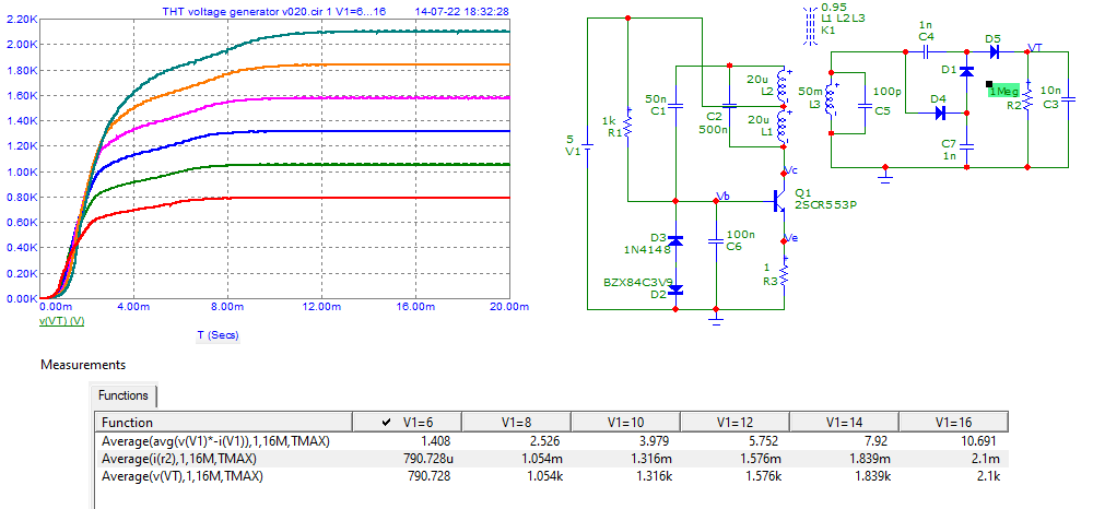
You should "perhaps" try something like this.
As example. Note that the voltage supply can adjust the High Voltage needed.
Average current simulated until 2 mA.
Be sure to check all component's specifications ...

enter image description here

\$\endgroup\$

Your Answer

By clicking “Post Your Answer”, you agree to our terms of service and acknowledge you have read our privacy policy.

Not the answer you're looking for? Browse other questions tagged or ask your own question.