This is a corollary to the other answers, just in case you're wondering why you can't use unbuffered RC sections.
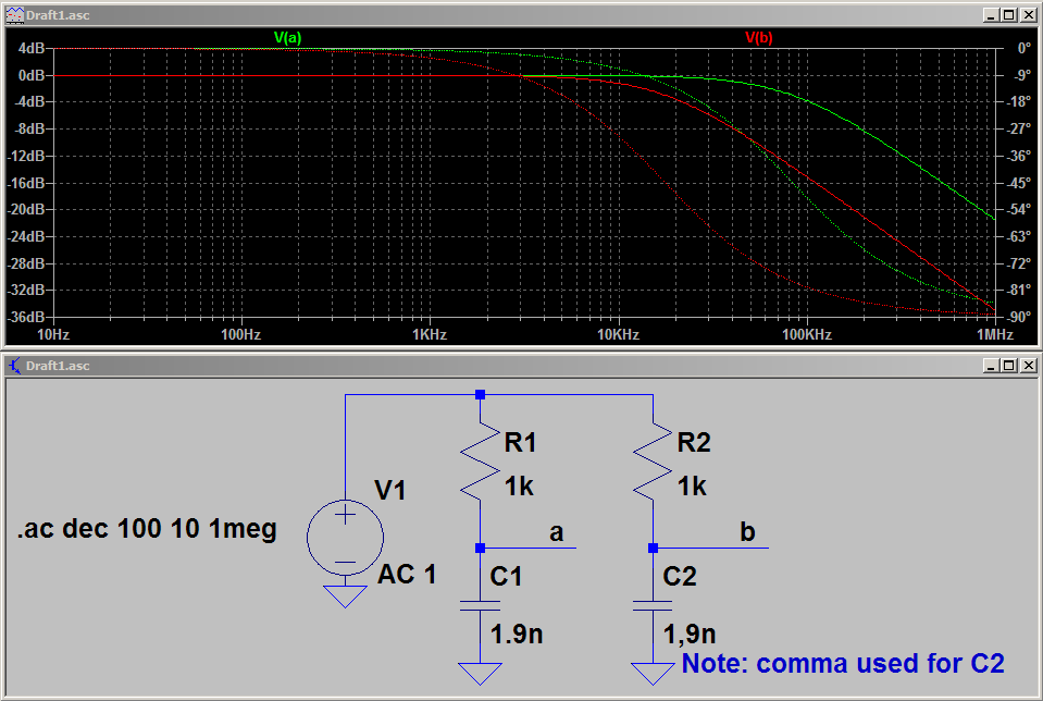
An RC filter, by itself, is a 1st order system. When buffered 1st order stages are added (all the same, for simplicity), it is possible to make a filter whose transfer function is:
$$H(s)^N=\left(\dfrac{\dfrac{1}{RC}}{s+\dfrac{1}{RC}}\right)^N=\dfrac{1}{(sRC+1)^N} \tag{1}\label{1}$$
Suppose only two sections are considered. Then, the transfer function will be a 2nd order whose \$Q=0.5\$ and you will never be able to exceed it. For \$R=1,\;C=1\$:
$$H(s)^2=\dfrac{1}{(s+1)^2}=\dfrac{1}{s^2+2s+1} \tag{2}\label{2}$$
For an unbuffered 2nd order filter, the transfer function will be (you can derive this however you wish):
$$G(s)=\dfrac{1}{s^2+3s+1} \tag{3}\label{3}$$
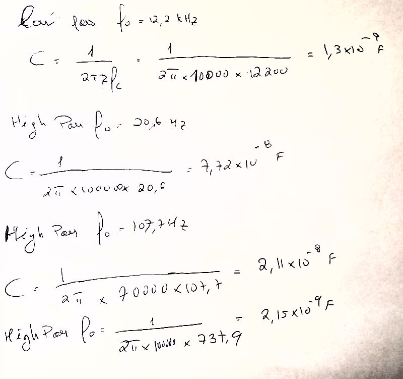
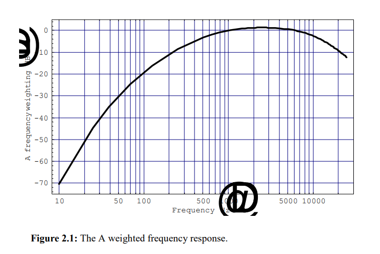
Here \$Q=0.33\$ and it will never go above this. This is why your attempt at "gluing" RC sections would never be able to achieve an active filter's response -- it will never have a high enough \$Q\$. It's also the reason why you see the filters represented as triangles in the 1st picture: they are meant to be active filters. Also, there's a matter of gain, since your last picture shows a slight gain at the peak. You might be able to achieve peaking with RC filters, but its not a practical solution. A pure passive RC network will always have attenuation due to the finite impedances of the input and output.
Also, see @swineone's answer for a way to optimize the overall filter.


