2
\$\begingroup\$

Below is the transfer function of the two cascaded first-order high-pass filters (each with 20.6 Hz cut-off frequency) and their circuit:

enter image description here

enter image description here

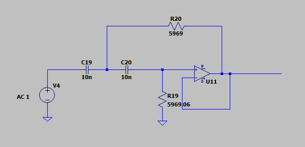
And then there is the transfer function of the second-order high-pass filter (with 20.6 Hz cut-off frequency) and its circuit:

enter image description here

enter image description here

Both transfer functions (cascaded and sallen-key) show the same response in Matlab.

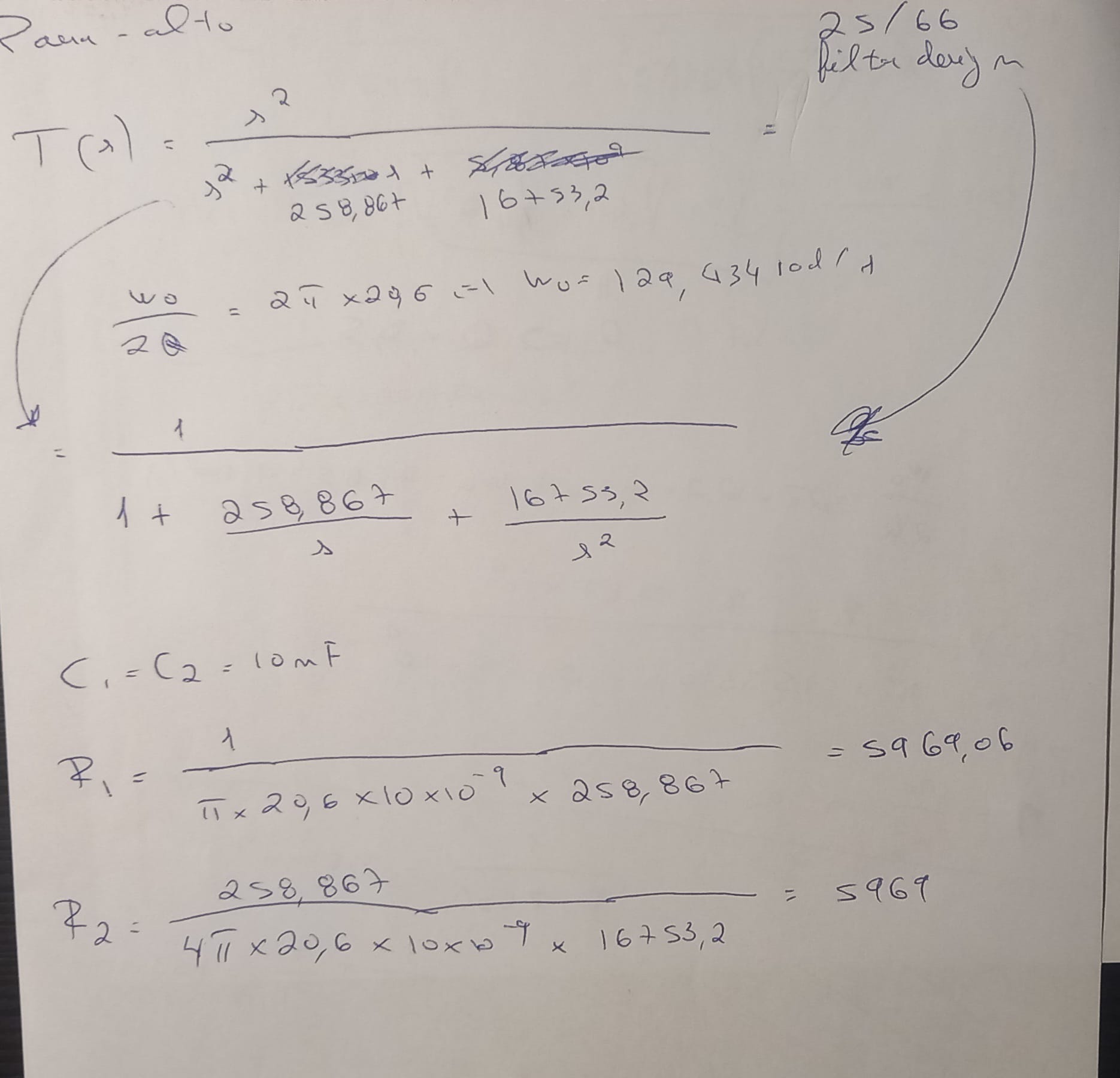
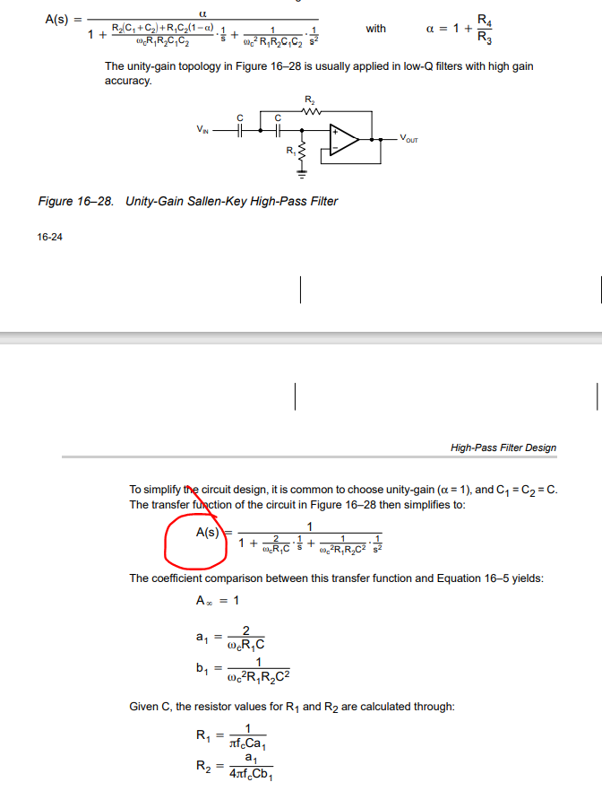
The values for the resistors were computed using this info:

enter image description here

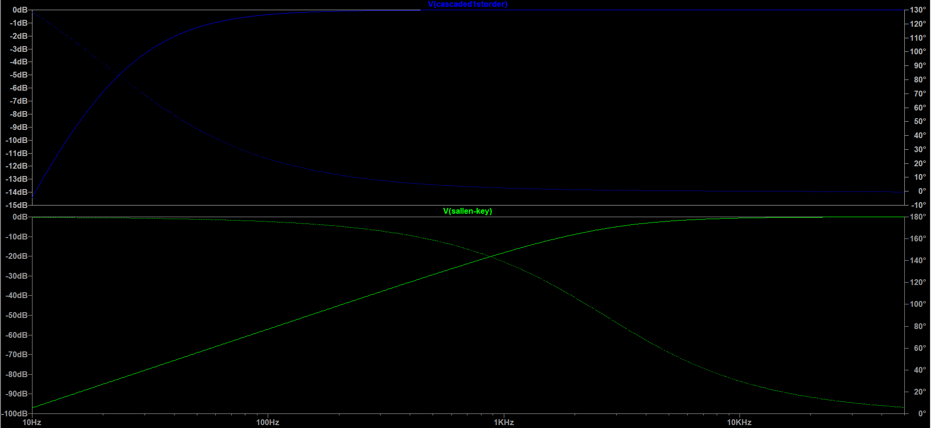
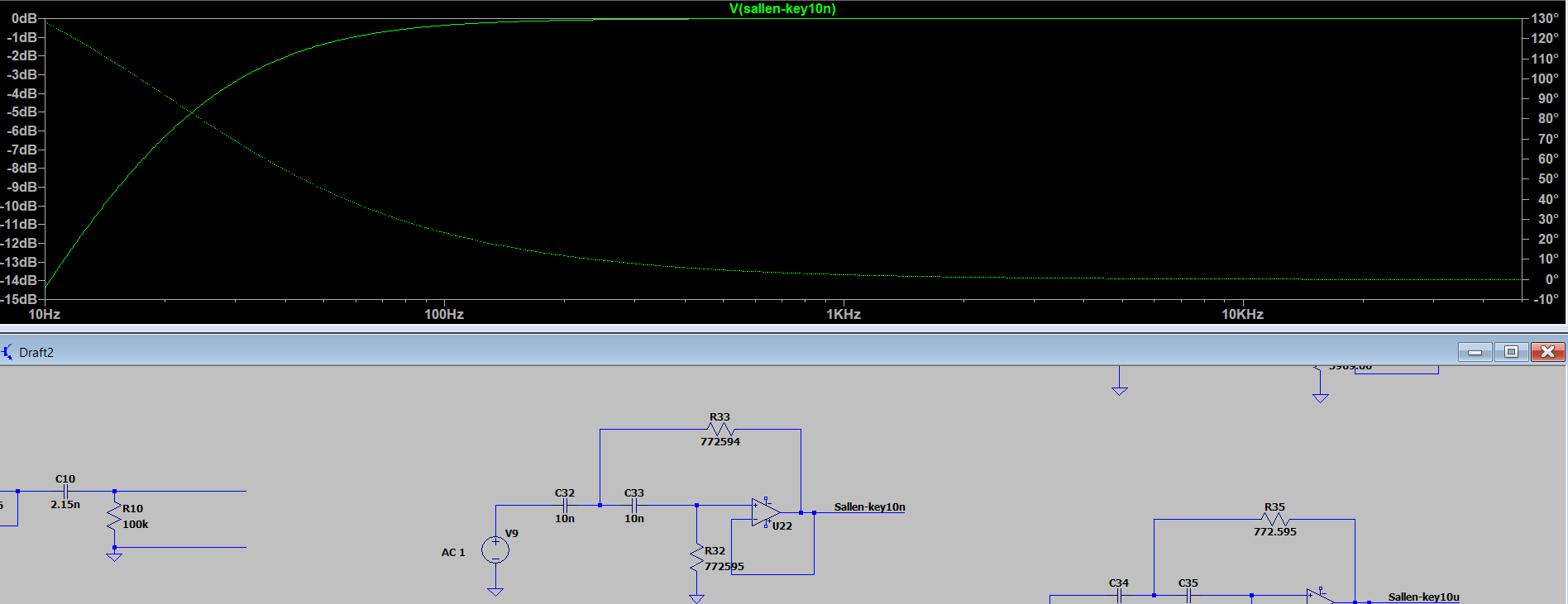
In LTspice I get this response:

enter image description here

Why are they different?

Note: The op amps used are ideal ones, that's why they dont have any supply connected

Edit:

I was told here that i need to calculate the resistors and capacitors values based at the highpass filter cut frequency ( at 20.5 Hz) with Q=0.5. That's what i did. In the second image i put here i used Q=0.5, i just didn't put the values there.

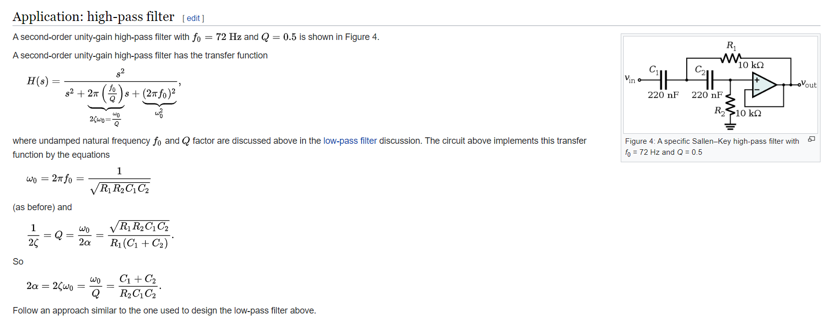
Even if i follow a different method to obtain the transfer function, like this one taken from wikipedia:

enter image description here

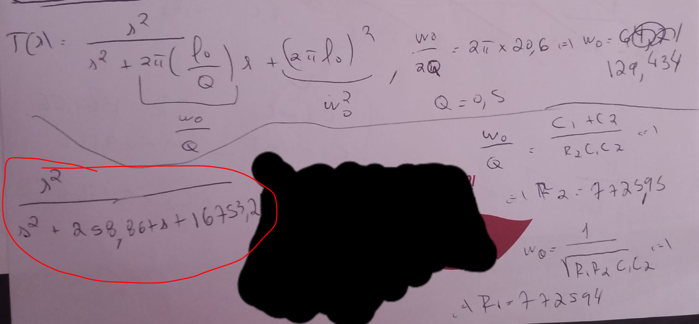
This is what i did:

enter image description here

With fc = 20.6Hz and Q = 0.5 i get the same transfer function.

I used C = 10nF and got 772594 ohms for the resistors (ignore the , there ). If i put that in LTspice i get the same response as the cascaded one.

enter image description here

So perhaps the problem is in the attribuition of the R1 and R2 value from that first document i have shown here.

\$\endgroup\$
1
  • \$\begingroup\$ Did you use power supplies for the opamps? If yes, why not show the entire schematic, not just what you perceive to be a "concept". Nobody can give accurate responses based on concepts. \$\endgroup\$ Commented Jul 22, 2022 at 6:43

2 Answers 2

3
\$\begingroup\$

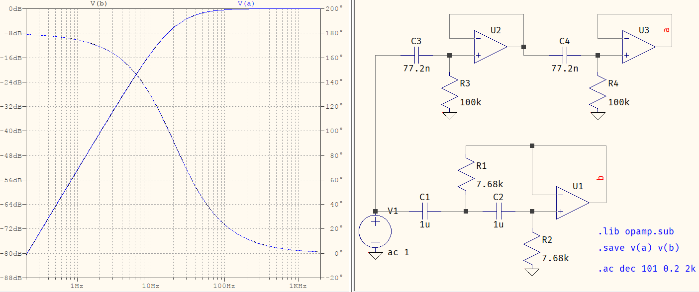
It looks like your conversion to the Sallen-Key topology was done by simply reusing the values of the resistors and the capacitors, but that's not how it works. You need to calculate them based on the requirements, and those are: a highpass filter at 20.5 Hz, with Q=0.5 (two buffered RC sections). With that in mind, you can either calculate the values by the formulas you have there, or use this very reliable site to determine the values: 7.68 kΩ and 1 μF, in duplicate. Now you can verify the results:

SK matches RC

I've used your values for the buffered RC stages, and the results almost overlap. Almost, because the linked site uses standardized values (thus some minor rounding errors), whereas your capacitors are not (no such standard value of 77.2: either 75 or 82 for E24.

\$\endgroup\$
5
  • \$\begingroup\$ See my new edit, i think the problem was in the equations used for the resistors. Perhaps in that document they're not right? \$\endgroup\$
    – Scipio
    Commented Jul 22, 2022 at 12:46
  • 1
    \$\begingroup\$ @G0tBlackOps It's difficult to say but, if you have the transfer function all you need to do is to make a system of equations and solve them:$$\begin{cases}\dfrac{1}{R_2C_1}+\dfrac{1}{R_2C_2}&=\dfrac{\omega}{Q} \\\dfrac{1}{R_1R_2C_1C_2}&=\omega^2\end{cases}$$. If you impose \$C_{1,2}\$ then the results come out as:$$\begin{cases}R_1&=\dfrac{1}{Q\omega(C_1+C_2)} \\R_2&=\dfrac{Q(C_1+C_2)}{\omega C_1C_2}\end{cases}$$. For \$C_1=C_2=1\;\mu\text{F}\$ you get \$R_1=R_2=7763.656\;\text{k}\Omega\$. In the answer it's rounded for E96. \$\endgroup\$ Commented Jul 22, 2022 at 13:15
  • \$\begingroup\$ @a concerned citizen If instead of having two first order filters with identical cut frequencies i had two first order filters with different cut frequencies how would i proceed with transforming from two first order stages to a single second order stage using Sallen-key configuration? How do i find the new cut frequency and Q? \$\endgroup\$
    – Scipio
    Commented Jul 22, 2022 at 15:02
  • 1
    \$\begingroup\$ @G0tBlackOps Sounds like a new question but, in short, the same as before: you combine the two 1st order into a 2nd order. You won't have one \$\omega^2\$, you'll have \$\omega_1\omega_2\$. Q will be less than 0.5, so it will be an overdamped case. E.g. \$s/(s+2)\cdot s/(s+3)=s^2/(s^2+5s+6)\;\Rightarrow\;\omega=\sqrt6,\;Q=\sqrt6/5\$. You can also combine a lowpass and a highpass, just the same. \$\endgroup\$ Commented Jul 22, 2022 at 17:21
  • 1
    \$\begingroup\$ (When using @, the names must not contain spaces. Use it with @<TAB> to cycle between the available names. if none comes out then there is no need for @). \$\endgroup\$ Commented Jul 23, 2022 at 6:24
1
\$\begingroup\$

Two isolated (buffered) first-order filters and one integrated second-order filter should not have the same transfer function. The second order filter can have several configurations (Butterworth, Bessel, Chebyshev, etc.). Each configuration has different frequency and phase plots.

A second order Butterworth filter is the most similar to a single pole R-C filter. One way to tell that they are different is that for identical input signal amplitudes, the cascaded circuit will have an output level of -6 dB at the corner frequency, while the 2-pole Butterworth will be at -3 dB at the corner.

There are many filter tutorials and calculator websites that have the transfer functions for the most common multi-pole configurations.

\$\endgroup\$
3
  • \$\begingroup\$ I did what was suggest from this post - electronics.stackexchange.com/questions/627660/… To save some two op amps from the first 4 stages. I already did it from the low-pass filter and it worked fine. \$\endgroup\$
    – Scipio
    Commented Jul 22, 2022 at 0:46
  • \$\begingroup\$ I already did it for the first two stages (sallen-key for low pass filter) and it worked fine. I dont want to use Butterworth, Bessel, Chebyshev and so on because i will have a different response for the filter when it has to be equal to the original with all the op amps. \$\endgroup\$
    – Scipio
    Commented Jul 22, 2022 at 0:54
  • 1
    \$\begingroup\$ This is not correct: a 2nd order can mimic two RC section, buffered or not. They are not restricted to classical filter design such as Butterworth, Chebyshev, etc. So you can definitely "compact" two 1st order RC into one active 2nd order filter. All there is to do is to match the Q. \$\endgroup\$ Commented Jul 22, 2022 at 6:43

Your Answer

By clicking “Post Your Answer”, you agree to our terms of service and acknowledge you have read our privacy policy.

Not the answer you're looking for? Browse other questions tagged or ask your own question.