0
\$\begingroup\$

I am trying to build a transimpedance amplifier circuit on a PCB (as in the figure below). Circuit used for SPICE simulation

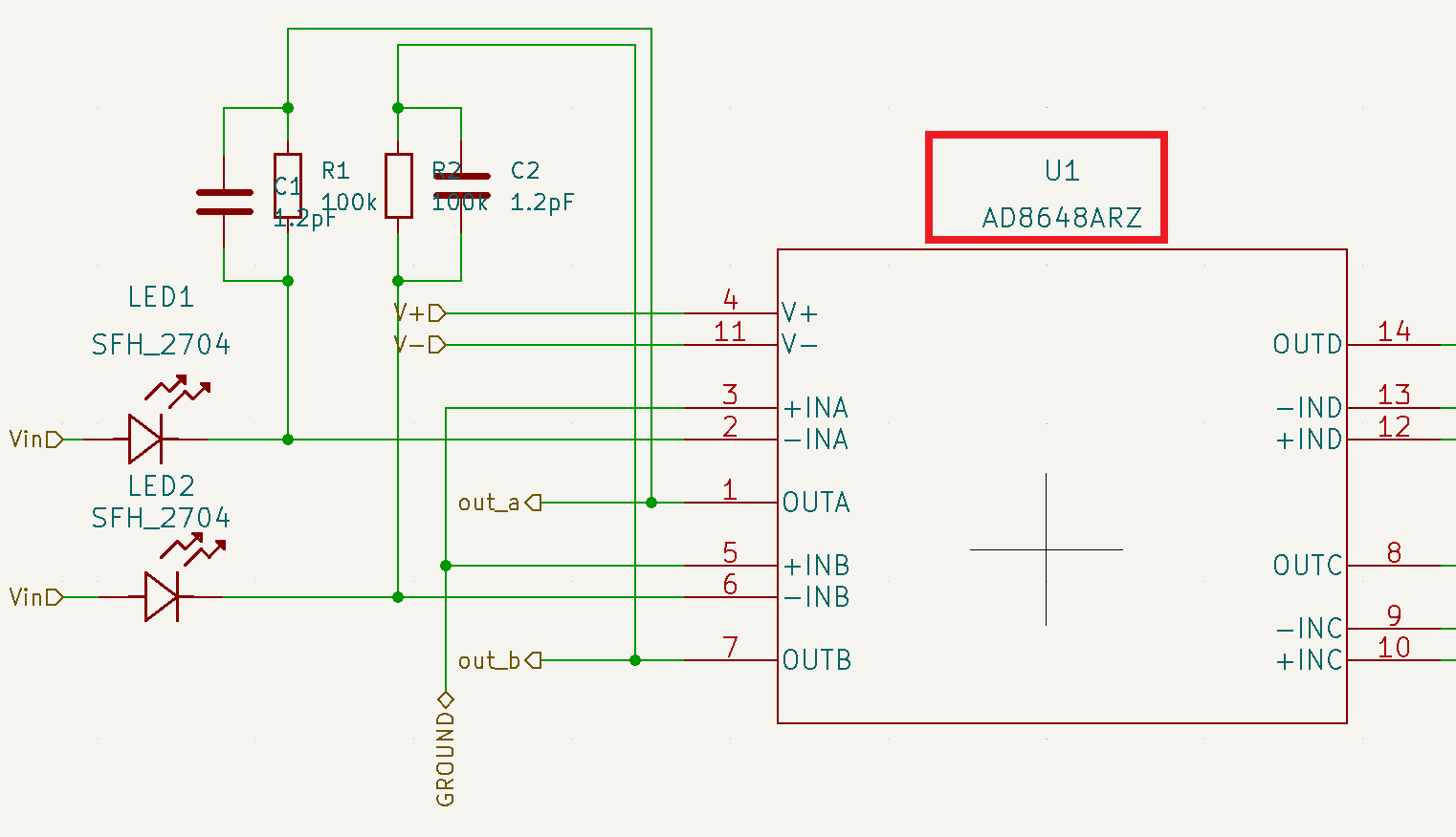
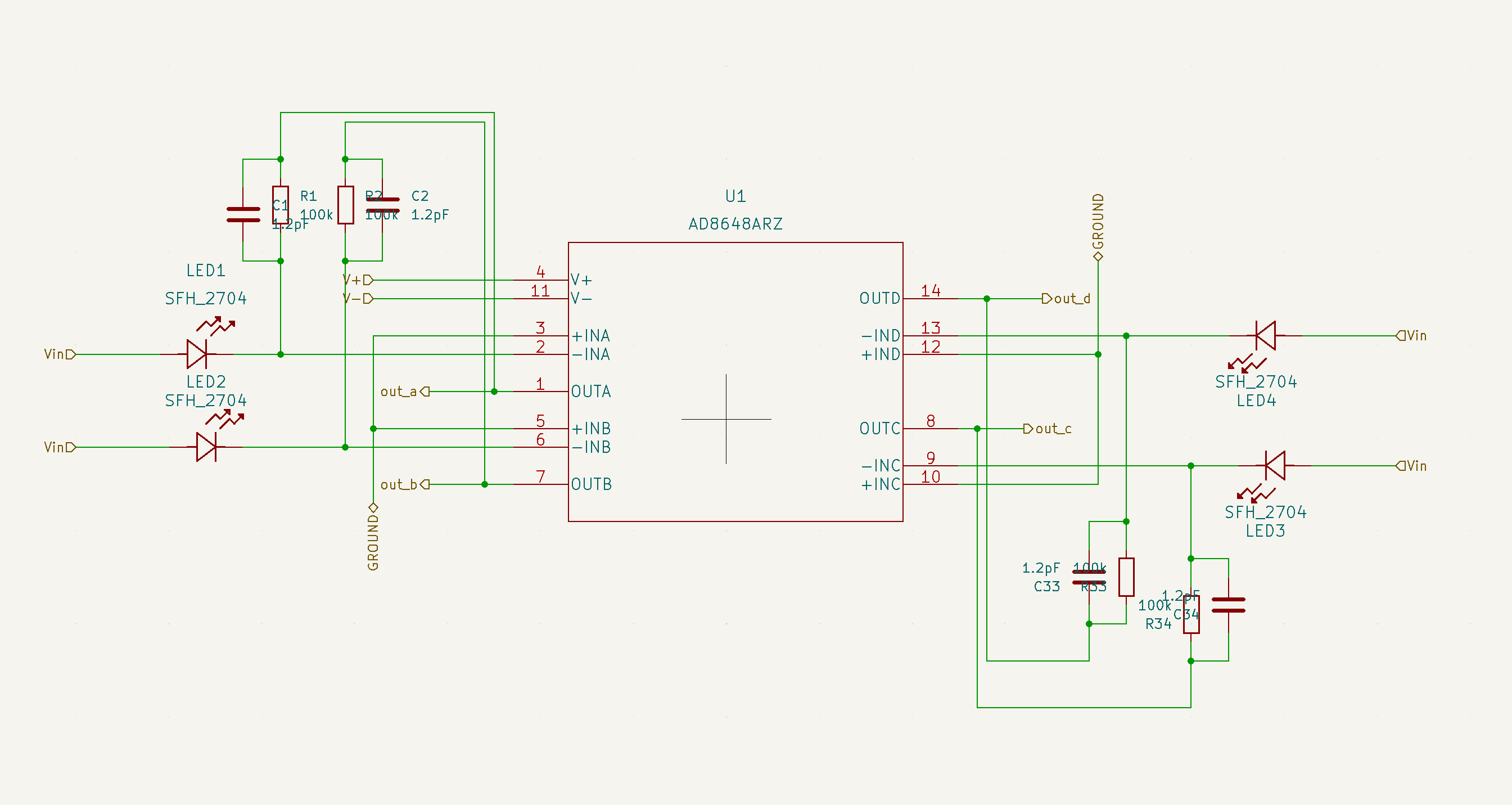
Although I have run a SPICE simulation and got the desired results, I wanted to test it out on a breadboard before ordering a PCB. I am using an op-amp chip AD8648 from Analog Electronics and SFH2704 as my photodiode (although it's simulated with SFH2701 in the figure above). Here's a picture of how the connections are in my KiCAD schematic

Kicad Schematic

Where Vin is -5V and +V and -V are +5V and -5V respectively.

Now my problem is that even though everything seems to work fine in my SPICE simulation, when I make connections on the breadboard, I am getting the following on the oscilloscope when measured between the output of the op-amp and the ground.

Oscilloscope observation

I am not sure what is happening here. I thought of testing out the same circuit with another op-amp I had lying around. So I tried the same circuit with AD712 and it showed a response with light as one would expect. This sinusoidal output stops when I remove the feedback connection. I tried out with different values of resistors and the frequency and the amplitude of this sinusoidal output remained the same.

I would be really grateful if someone could help me troubleshoot this problem.

\$\endgroup\$
2
  • \$\begingroup\$ Does it help if you increase the value of C1 a bit? \$\endgroup\$
    – user173271
    Commented Aug 17, 2022 at 14:46
  • \$\begingroup\$ You simulated a really small photodiode with almost no capacitance, but built the circuit with a larger photodiode that has a lot of capacitance and on a prototype board that will add even more parasitics. Likely that your C1 value is wrong for the real load and the amplifier is oscillating, but you should simulate this to be sure. \$\endgroup\$ Commented Aug 17, 2022 at 14:48

2 Answers 2

5
\$\begingroup\$

I would be really grateful if someone could help me troubleshoot this problem.
and

Where Vin is -5V and +V and -V are +5V and -5V respectively.

The AD8648 has an absolute maximum voltage rating (between V+ and V-) of 6 volts. You are applying 10 volts (+ and -5 volts). That's a serious show-stopper: -

enter image description here

Image from datasheet. Close up of your image: -

enter image description here

A lack of decoupling capacitors on the op-amp power pins is also a big no-no.

\$\endgroup\$
2
  • \$\begingroup\$ Thank you for taking the time to answer my question. I had misread the datasheet and thought that the supply voltage was 12V. I might have damaged a particular op-amp but the circuit works with a different one. As for the decoupling capacitors, the screenshot I shared is that of a subpage. I have multiple units of these and there are decoupling capacitors near the power supply connectors \$\endgroup\$
    – Nikhilesh
    Commented Aug 23, 2022 at 9:59
  • \$\begingroup\$ @Nikhilesh good man. Glad it's now working. \$\endgroup\$
    – Andy aka
    Commented Aug 23, 2022 at 10:00
2
\$\begingroup\$

Take a look at the AD8648 data sheet. Slew rate is a minimum of 11 v/usec.

Your input signal is at about 10 MHz, so each half of the waveform takes 50 nsec.

At 11 V/usec, you can only count on a voltage change of 11 x .05, or about .55 volts. This is right in line with your observed swing of 0.6 volts.

"So I tried the same circuit with AD712 and it showed a response with light as one would expect."

And what did you get? What do you expect? You haven't actually told us what you expect, and you haven't shown us what you got.

\$\endgroup\$
1
  • \$\begingroup\$ Thank you for taking the time to answer my question. My input signal was a lamp which one would assume to be a constant source but even if there were oscillations, it would be at the wall supply frequency. Very far from the 10MHz that would be needed. What I meant by the response for AD712 is that the circuit responds to light intensity changes. I am not interested in the specific response in this instance \$\endgroup\$
    – Nikhilesh
    Commented Aug 23, 2022 at 10:03

Your Answer

By clicking “Post Your Answer”, you agree to our terms of service and acknowledge you have read our privacy policy.

Not the answer you're looking for? Browse other questions tagged or ask your own question.