8
\$\begingroup\$

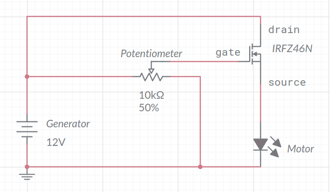
I've searched on the network for days but couldn't find a solution to my problem I hope you can help me. I want to create a DC motor speed regulator using IRFZ46N as a power MOSFET and a 10k potentiometer.

I created this circuit and tested it on a breadboard:

enter image description here

The circuit doesn't work properly and I faced 2 problems:

  1. The voltage at the source pin is about 10V, instead on the drain and gate pin the voltage I measure is correct (12V). So seems like the MOSFET stole 2V, is very strange because the RDS(on) is very very low according to the datasheet:

    2

I also noticed that if I follow this relationship Vgs > Vt and Vds < (Vgs - Vt) so I reduce the drain voltage this problem doesn't appear. Maybe I'm working in saturation ? I don't know if or why this can be the solution.

  1. The MOSFET gets very very hot, the power (i think) is about 16W (1.6A takes motor times 10V = 16W), maybe I can use multiple parallel IRFZ46N with heatsinks?

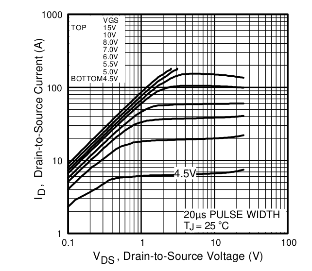
This is the typical output characteristic but I don't know how to read the graph:

enter image description here

I'm a newbie in MOSFET's world so I would be very grateful If you can help me and explain where I'm wrong. Thanks in advance.

\$\endgroup\$
4
  • 4
    \$\begingroup\$ You're reinventing the wheel, and the wheel you're inventing isn't going to work very well. If this is an academic exercise to understand MOSFETs and such, by all means go for it! If your interest is not in the electronics aspect, and instead you only care about controlling the motor speed, suggest you just get a pre-built unit. Something like this would do the trick pretty nicely: amazon.com/DC-Motor-Speed-Controller-Kit/dp/B013TA1C0Y That's just one of a zillion possible options. \$\endgroup\$
    – Kyle B
    Commented Aug 19, 2022 at 19:05
  • 3
    \$\begingroup\$ And switch the positions of the MOSFET and the motor. You can't get adequate voltage on your gate in this configuration. The voltage across the motor raises the MOSFET's source well above ground. Andy's answer below shows the proper order... MOSFET source tied to ground, Motor tied to MOSFET drain. \$\endgroup\$
    – Kyle B
    Commented Aug 19, 2022 at 19:12
  • \$\begingroup\$ @KyleB Just academic \$\endgroup\$
    – minghierid
    Commented Aug 20, 2022 at 12:47
  • \$\begingroup\$ Thanks a lot to all who replied, you helped me to understand a little bit more something that in my books is not very clear providing even better solutions. \$\endgroup\$
    – minghierid
    Commented Aug 20, 2022 at 18:06

5 Answers 5

10
\$\begingroup\$

To help you understand let me go through some MOSFET specs.

  1. You found \$R_{DS}(on)\$ in the datasheet. Just below that line is \$V_{GS}(th)\$ which has a minimum of 2V and a maximum of 4V. Therefore the voltage drop from gate to source must be greater than 4 volts to start conduction. There is no control over this value, when you buy a FET then \$V_{GS}\$ will be somewhere between those values. Based on your point 1, \$V_{GS} = 2\$V the minimum.
  2. If you look closely in the datasheet for \$R_{DS}(on)\$, you will see the conditions at which it was measured:\$V_{GS}=10\$V and \$I_{D}=28\$A. The low \$R_{DS}(on)\$ occurs only at high gate-source voltages.
  3. Looking at the chart you supplied, the solid lines represent a specific gate-source voltage. The lowest is 4.5V, the highest is 15 V. If we follow a vertical path along, say, the 1 volt \$V_{DS}\$ path, then the drain current increases as the gate-source voltage increases demonstrating that the drain-source resistance \$R_{DS}\$ decreases with increasing \$V_{GS}\$.

The transistor gets hot because \$R_{DS}(on)\$ is not small for the values of \$V_{GS}\$ that you are using. So yes, you could put heatsinks on and/or parallel several FETS to keep the temperature low.

If you adjust the potentiometer so there is 5V across the motor, the voltage from gate to ground must be 7V to 9V, \$V_{motor}+V_{GS}(th)\$. The 16W from your point 2 is the power dissipated by the motor. To find the power dissipated by the transistor (as heat) we need to know the voltage drop across it, namely $$V_{DS} = 12 - 10 = 2$$V Then calculate the FET power dissipation.$$P_{DS} = (20)(1.6) = 3.2W$$

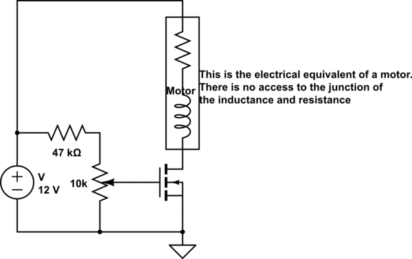
Another way to explore the FET drive is putting the motor in the drain circuit as shown below.

EDIT: The 47k resistor will reduce the sensitivity of the potentiometer. It will also reduce the maximum voltage that you can apply. Experiment with different values. END EDIT

schematic

simulate this circuit – Schematic created using CircuitLab

Cheers for exploring.

These are great circuits for introductory exploration of FETs. Except for on-off control they are not contenders for serious work. Too much power loss. A better way for speed control is though pulse width modulation (pwm). The complexity is greater but power efficiency is nearly perfect.

\$\endgroup\$
7
  • 3
    \$\begingroup\$ Using voltage from a pot to control an n-FET on the low side is tricky - it won’t have a nice linear action. It’ll pretty much be on or off. This would work if current feedback sensing were used. \$\endgroup\$ Commented Aug 19, 2022 at 20:42
  • 2
    \$\begingroup\$ @hacktastical: True: The OP is just exploring the very basics. But I take your point about the pot. I will modify the schematic a bit. It is still a good exercise. \$\endgroup\$
    – user319836
    Commented Aug 19, 2022 at 20:49
  • \$\begingroup\$ I also tried connecting the motor on the drain terminal but it only works completely on or off - I don't know why - so I'm not able to regulate the speed in some sense. \$\endgroup\$
    – minghierid
    Commented Aug 20, 2022 at 13:18
  • \$\begingroup\$ @DavideDemarino: Now that you have tested the two configurations. I suggest that you investigate speed regulation using pulse width modulation (pwm). It is the most common method of speed control. It has high efficiency. There are plenty of articles found with a google search. \$\endgroup\$
    – user319836
    Commented Aug 20, 2022 at 16:55
  • \$\begingroup\$ Due to using Arduino I'm familiar with PWM but I chose to try alternative solutions, just for learning and exploring. After following your - and others' - advice the next obstacle to jump is to provide 12V to the drain terminal even if I'm using a 24V generator. I tried to create a voltage divider using resistors but the current was very weak to turn on the motor; so I think I will try to use an LM78012 voltage regulator to give 12V to the drain terminal, the challenge now is to increase the voltage regulator output current, I need more than 1 A. I don't know if it works but I really hope so. \$\endgroup\$
    – minghierid
    Commented Aug 20, 2022 at 17:17
8
\$\begingroup\$

As always, to fully activate an N channel MOSFET, the gate voltage must be several volts higher than the source voltage. If you want your switched source voltage to be close to 12 volts then you need to raise the gate voltage to possibly 14 or 15 volts (load dependent) or, better still 20 volts with respect to ground.

Your circuit works like that because it is a source follower. The normal (and basic) way of switching on and off a motor is to use what is known as a common-source circuit. This time, source connects to ground and the gate voltage can be any convenient value to give you current control of your motor but, now your motor will connect between drain and 12 volts.

But remember, if you wish the MOSFET to control a motor that is (say) taking a 2 amps at 6 volts, the MOSFET will behave like a resistor dropper and dissipate 12 watts. Is this what you want?

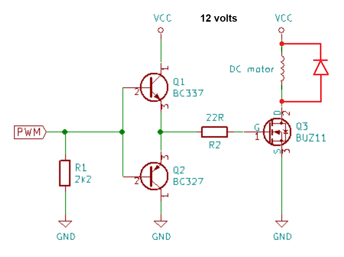
I can't answer that other than to tell you that most motor controllers operate with the MOSFET being turned on and off at kHz rates. This can give the illusion of simple linear motor control without the heavy power dissipation of simple linear motor control. A few more components needed is the price to pay (example): -

enter image description here

Image from this question. I've added the flywheel diode in red. The circuit can be simplified a little but more thought is needed to effectively make that simplification.

\$\endgroup\$
6
  • \$\begingroup\$ You could do with a flywheel diode across the motor or there will be a high voltage across the FET when it turns off and the energy in the motor inductance will be lost. At high frequencies the presence of C3 will cause high peak currents in the FET. \$\endgroup\$ Commented Aug 19, 2022 at 20:37
  • \$\begingroup\$ @KevinWhite it's not ideal is it. The cap will limit the back emf but, it's dependent on motor current and motor leakage inductance or free-spinning. I'll amend that picture. Thanks very much. \$\endgroup\$
    – Andy aka
    Commented Aug 19, 2022 at 20:50
  • \$\begingroup\$ @KevinWhite Would a few tens or hundreds of ohms of resistance in series with C3 be useful? \$\endgroup\$ Commented Aug 20, 2022 at 15:29
  • \$\begingroup\$ @AndrewMorton - it would reduce dissipation but C3 is not necessary. \$\endgroup\$ Commented Aug 20, 2022 at 19:40
  • 1
    \$\begingroup\$ @Andyaka: I have used this circuit quite successfully. C3 is actually detrimental. The flywheel diode should be a Schottky diode. Regular diodes cause a spike on the gate through the Miller capacitance. This is due to minority carrier in the diode. I have found that Q1 and Q2 have sufficient internal resistance that R2 may not be necessary. What I have found beneficial is a 1uF ceramic from VCC to ground located close to Q1-C. It provides a local energy store for high speed switching transients for the gate. \$\endgroup\$
    – user319836
    Commented Aug 21, 2022 at 3:50
5
\$\begingroup\$

Why does it heat up? The FET isn’t being turned on fully. Instead, the source (terminal facing the motor) is following the gate by one Vgs threshold voltage (between 2 and 4 volts).

So with your pot at 100%, gate voltage will be 12V while source will go no higher than 8-10V. That means up to 4V of drop across the FET at your max current, which will be shed as heat. Even at the lower pot settings there is still drop across the FET which sheds power.

This isn’t all bad: what you’ve designed is a circuit called a source follower which indeed can be used as a voltage control, so long as you understand that it will have IR drop in the FET. It gives a nice, linear voltage control in a simple fashion. Ok for a light load, but not so great an idea for a motor with significant load.

There are some techniques using current sensing that could yield better results with linear control, but really the easiest way to get better efficiency is to use a PWM drive on the FET, and ensure that the gate drive is large enough to fully turn on the FET.

And, within PWM there are some options. If you move the n-channel FET to the low side, this allows using simple logic to drive the gate from something like a 555 or a microcontroller. This is a popular ‘fan control’ circuit which is easy to use.

If you need high-side drive using a p-channel FET with a level shifter is a good choice.

If you insist on using an n-FET and high-side drive you’ll need to add a bootstrap to make the high-side drive voltage plus use a level shifter.

\$\endgroup\$
3
  • \$\begingroup\$ And for what it's worth, N-type MOSFETs have lower RDS(on) characteristics compared to P-type MOSFETs. For this reason, it's preferable not to use a P-type MOSFET as the high-side switching element because they tend to dissipate much more power (they waste energy and run much hotter), and to use instead an N-type MOSFET in conjunction with a gate drive IC that provides the necessary gate (dis)charging current and gate voltage bootstrapping, as you've mentioned. \$\endgroup\$ Commented Aug 19, 2022 at 21:03
  • 2
    \$\begingroup\$ The Rds(on) difference for n vs. p isn’t as much as it used to be, and it can be overcome by making the p device larger. For most work this is enough; it only comes into play at very large currents, at which point you have a bunch of other problems to solve. \$\endgroup\$ Commented Aug 19, 2022 at 21:18
  • \$\begingroup\$ @JimFischer Just what hacktastical said. Nowadays there are lots of discrete PMOS that are almost as good as NMOS, if you are not dealing with the most demanding applications. The first that comes to my mind is the AO3401. 85mohm Rdson @ Vgs=2.5V (so a logic level mosfet suitable for 3.3V systems), suitable for PWM apps. If you use it with higher Vgs you can have lower Rdson. They are used everywhere in BMS systems and as high-side soft switch circuits without the hassle of NMOS high-side switch drivers. \$\endgroup\$ Commented Aug 20, 2022 at 9:12
4
\$\begingroup\$

What you have built is a "source follower", also known as a "common drain" configuration.

It seems that you expected the source to follow the drain volt-for-volt, with no difference between the two potentials, but that's not what happens.

This transistor cannot possibly be "on" if the gate-to-source potential difference (\$V_{GS}\$) is less than the minimum potential difference required for it to be "on". That potential difference, between gate and source, necessary for the MOSFET's channel to begin conducting, is called the "threshold", labelled \$V_{TH}\$, or \$V_{GS\_ON}\$, or something like that.

Consider this: if the voltage across the load (a motor in your case) rises, the MOSFET's source potential must also rise, bringing it closer to gate potential, so the difference \$V_{GS}\$ decreases. Conversely, if the voltage across the load decreases, source potential falls, increasing the difference \$V_{GS}\$.

With that in mind, see that when \$V_{GS}\$ is too small, the MOSFET switches off, causing the current through, and the voltage across the load to decrease, which in turn increases \$V_{GS}\$. In other words, a decrease in \$V_{GS}\$ results in a response that increases \$V_{GS}\$, in opposition to whatever perturbation caused the initial decrease.

And vice versa. The transistor adopts an equilibrium state, where \$V_{GS}\$ is just enough to conduct, the "threshold" value I mentioned, \$V_{TH}\$.

This means that a common drain configuration like yours will always maintain a condition where the potential difference between gate and source, \$V_{GS}\$ is pretty much constant, equal to \$V_{TH}\$, which seems to be about 2V in your case. That's why you "lose" 2V.

That's a small price to pay for the huge benefit that you get from this setup, which is that you may control the voltage across a very "heavy" load at the source, which may require a lot of current, using a voltage at the gate drawing almost no current at all.

It has the disadvantage that if you wish for +12V to appear at the source, you must apply +14V to the gate, due to \$V_{TH}=2V\$ in this case.

\$\endgroup\$
1
\$\begingroup\$

I think you are using an inoptimal way of adjusting motor speed.

If you have 12 volts, and want your motor to have let's say 6 volts, there are two ways you can achieve that.

One possibility is using a transistor to drop voltage. In this case, the transistor will look like a resistor whose value is correct to drop the 6 volts depending on the current. Like any resistor, it will dissipate heat. If this is done using a BJT, you usually use it in emitter follower configuration. You are now using a MOSFET, which is not as commonly used to drop voltage, but what you have is a source follower, a MOSFET equivalent of the BJT emitter follower. Usually this kind of control is not favored, because of the heat problem. Heat requires expensive heatsinks, and also loses precious energy to a non-useful form.

Another possibility is pulse width modulation, for example by making an oscillator out of 555 and using the potentiometer to vary duty cycle if you want the possibility to adjust speed. Cycle the MOSFET at a high frequency so that the motor will have 0 volts half of the time, and 12 volts half of the time. It has 6 volts average therefore. The rotational inertia in the motor is large enough to make a "50% 0 volts, 50% 12 volts" control look exactly like "100% 6 volts" control, provided that the switching frequency is large enough. Since a motor is an inductive load, you may want to add an anti-parallel diode to provide current path for the sudden voltage caused by the inductor when current would want to stop. The MOSFET already has an anti-parallel body diode, but a separate diode won't hurt.

The PWM control can also be used for LED lights (but then if the switching frequency is low, most sensitive users could get a headache, and some digital cameras can become confused since only the most expensive models can time the shutter release exactly at the moment the LED lights turn on) and for resistive loads. If controlling a load that wants continuous voltage, such as using 12 volts to supply power to a 5 volt microcontroller, then you use an inductor and capacitor to smooth out voltage variations by using a buck converter, in which case control is slightly more complicated as due to possibility of discontinuous mode you can't assume that providing 12 volts 41.667% of the time would always give you 5 volts. Usually you compare P% of the output to an X volt Zener (or similar) reference, amplify the error, and use that error to determine switching duty cycle in a feedback error compensation circuit.

\$\endgroup\$

Your Answer

By clicking “Post Your Answer”, you agree to our terms of service and acknowledge you have read our privacy policy.

Not the answer you're looking for? Browse other questions tagged or ask your own question.