1
\$\begingroup\$

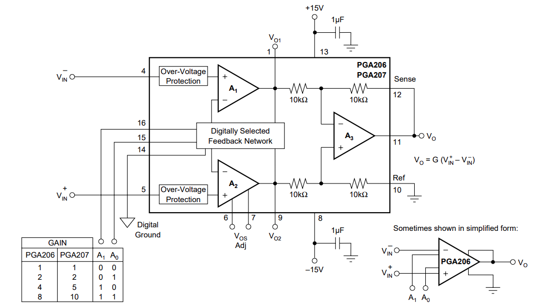
I have mistakenly used an instrumentation op-amp (PGA207) in the place of a normal op-amp in my design, so now I have to make adjustments to my circuit. A snippet of the datasheet from the op-amp I used is shown below:

PG207 Instrumentation op-amp

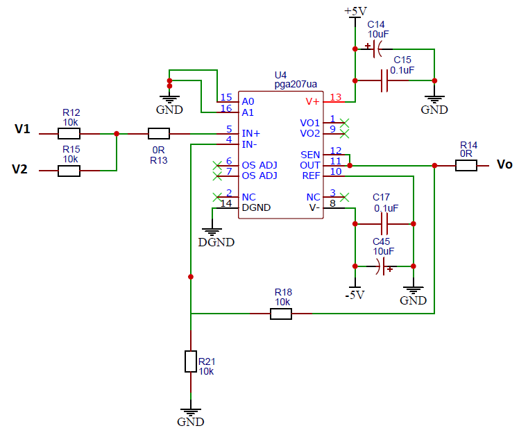
I tried to use this op-amp for a non-inverting summing amplifier as shown below:

Faulty summing amp design

I now know that my external feedback loop interferes with the internal loop circuitry. In what way can I mod the above circuit so that it will still serve as a summing amplifier for voltages V1 and V2?

\$\endgroup\$
2
  • \$\begingroup\$ Are you trying to physically modify a board that was built with the incorrect circuit, or are you just trying to update the schematic so that the circuit is correct? The latter just requires some redrawing but the former will require images of the PCB design so we can see where it is possible to physically modify the circuit. \$\endgroup\$
    – Null
    Commented Aug 30, 2022 at 19:54
  • 1
    \$\begingroup\$ Remove R18 and set A0 to 1. \$\endgroup\$
    – D.A.S.
    Commented Aug 31, 2022 at 1:54

2 Answers 2

2
\$\begingroup\$

As implied this answer, all you need to do is to remove R18.

Ideally, also reduce R21 to about 5K to match the resistances seen by each input (more important if you are operating at high temperature).

With inamp gain of 1, the output will be (V1 + V2)/2.

\$\endgroup\$
0
\$\begingroup\$

I now know that my external feedback loop interferes with the internal loop circuitry. In what way can I mod the above circuit so that it will still serve as a summing amplifier for voltages V1 and V2?

That was an expensive mistake. PGA207 is a $30+ part. You can easily get same performance in your application using $3 worth of parts, or less.

Given the relatively low prices of board manufacturing today, I would say you might be losing money by spending any time thinking about using this circuit as-is.

I bet you it'll be overall cheaper for you to tweak the board to use a normal op-amp. You're not even using the adjustable digital gain feature on the PGA207.

PGA207 is a $30+ instrumentation amplifier with digitally adjustable gain, when a comparable resistor-adjustable gain instrumentation amplifier would have cost $5 or less, say AD623, AD8226, AD8221, etc. (while still making the same mistake).

Almost any modern precision op-amp costing about $3 in small volumes will beat PGA207's performance in the system anyway, and you can do even better if the voltages are limited to +/-2.5V - since there's a whole slew of excellent R-R op-amps that work up to 5V.

\$\endgroup\$
1
  • \$\begingroup\$ Thanks for the comment. I realize it was an expensive mistake. In the schematic I tie the digital gain pins to ground, but I do intend to use them in a future version. As mentioned in @Null 's comment, the board is already manufactured, since I wanted to do rapidly prototype the board and at the time I believed the PGA207 was a suitable candidate. Will look at alternatives for the next one! \$\endgroup\$ Commented Aug 31, 2022 at 5:59

Your Answer

By clicking “Post Your Answer”, you agree to our terms of service and acknowledge you have read our privacy policy.

Not the answer you're looking for? Browse other questions tagged or ask your own question.