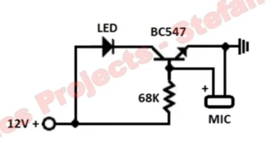
I found this circuit in many places:
The same resistance (68 kΩ) works with 3.7 V, 9 V, and 12 V. The LED flashes with the mic input (say with music).
I tried with an old Samsung earphone mic, didn't work, I tried connecting the mic output of my working earphones, didn't work. I am not sure where am I wrong.
I don't have a 68 kΩ resistor. What I have is a 5 V power supply and a 56 kΩ resistor. I tried joining two in series.
Can anyone explain how this circuit works so that I can calculate the resistor values I need to make this work with a different mic, resistance and voltage? Is this circuit working as a switch or as an amplifier?
Added - background: I have a electret mic from old earphones.
I want to glow the led with music beats, that in turn would fall on an LDR that is attached to a BT136 triac's MT2 and Gate, in series with a resistance. Eventually it will glow or turn off an ac light with music beats.
My BT136 circuit is working fine, but I am not able to accomplish the DC part of this project. I am searching for circuits with least components because I have access to limited components in my area. Can my goal be achieved anyhow by using the BT136 and the mic, with minimal components?

