1
\$\begingroup\$

I recently recycled a 070XF01 voltage regulator from an old PCB. I want to make a 5 V power supply for a small project to power an ESP32 dev board.

I'm still new to reading datasheets and this has really stumped me. Also I can't find any tutorials online for a 4-pin variable voltage regulator circuit.

My question is, how do I set Vref? I'm looking to supply the circuit with a 2s, 7.4 V battery, and would like to get 5 V output preferably.

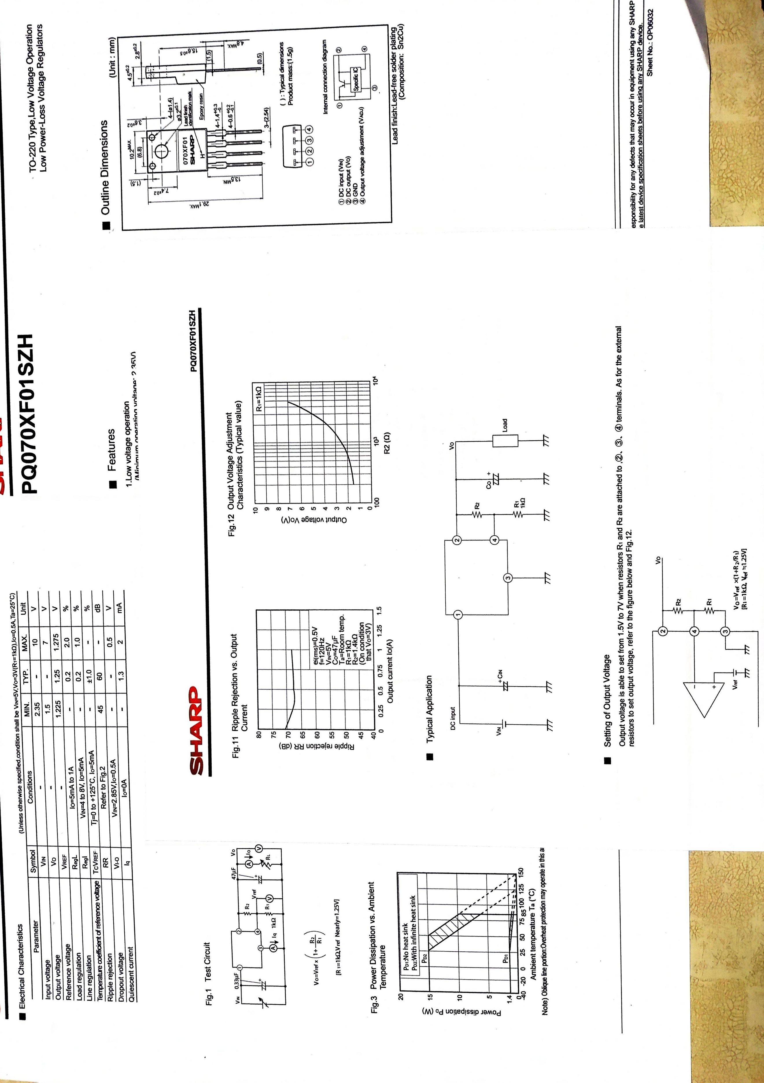
Here is a collage of the datasheet:

here is a collage of the datasheet

\$\endgroup\$
3
  • \$\begingroup\$ Looks very similar to LM317. You'll place a voltage divider from the output down to the adjust pin and it should have a 1.25V drop across the upper resistor. Why use such an inefficient old thing for a battery application though? \$\endgroup\$
    – Lundin
    Commented Sep 7, 2022 at 14:09
  • \$\begingroup\$ Thanks. ill look into it abit more when i get home from work. On why im using this approach, im wanting to make it portable for automating something on a remote controll aircraft. also it is the only regulator i have and im cheaping out so... ;-) \$\endgroup\$
    – Logan
    Commented Sep 7, 2022 at 14:22
  • \$\begingroup\$ Well, "cheaping out" might mean that it doesn't fully discharge the batteries leading to shorter battery life - depending on chemistry. NiMH for example should ideally be discharged before charging them again. With 5V supply you get around 5V + 1.25V = 6.25V as minimum input voltage. \$\endgroup\$
    – Lundin
    Commented Sep 7, 2022 at 14:33

1 Answer 1

2
\$\begingroup\$

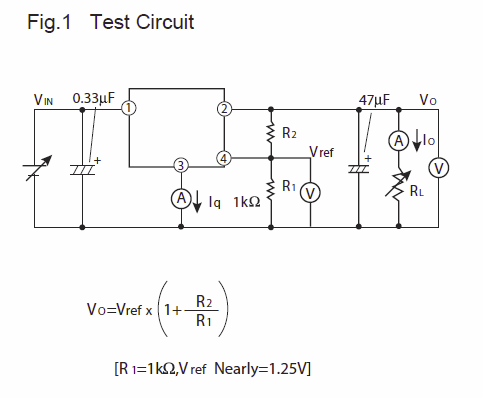
There is an example and even a formula in the datasheet:

enter image description here

Basically these old things work by having a specified fixed voltage across the resistor named R1, in this case 1.25V. So if you want 5V as output you have to pick a voltage divider that gives 1.25V across R1 and 3.75V across R2. So we can conclude that R2 needs to be 3 times R1 without even reading that formula. For example R2 = 3k and R1 = 1k will probably work fine.

Then just use the cap values they suggest, 330nF on the input and 47uF on the output. You might also wanna add polarity protection further out to ensure that things don't go poof if you connect the battery backwards.

Note that you might have to measure the output voltage while applying a bit of load!

\$\endgroup\$
2
  • \$\begingroup\$ that makes sense now on the voltage divider. discharging my lipo is something i need to watch too, as iv noticed my batteries dont last very long. i cant wait to go try this and see what i get. although after reading through some info on the esp32 it looks as if it has a on board regulator, but i want to build this anyway and it would probably be better to rely on a external psu circuit. \$\endgroup\$
    – Logan
    Commented Sep 7, 2022 at 19:56
  • \$\begingroup\$ @Logan If you are using Lipo then you need a BMS to handle that. But the good news then is that you won't have to be concerned about fully discharging them. An entirely different possibility would be to use a switched regulator, which is way more efficient. There's pre-made ones as "drop-in replacement" for LM317 TO220 package. However, if this is a board with RF drawing power directly from 5V then it's not a bad idea to use a linear regulator. Cleaner RF supply at the cost of slightly shorter battery life. \$\endgroup\$
    – Lundin
    Commented Sep 8, 2022 at 9:27

Your Answer

By clicking “Post Your Answer”, you agree to our terms of service and acknowledge you have read our privacy policy.

Not the answer you're looking for? Browse other questions tagged or ask your own question.