0
\$\begingroup\$

I am trying to control a 24V load with a 5V Arduino pin. I once burnt an Arduino but couldn't find why. I am extra cautious now.

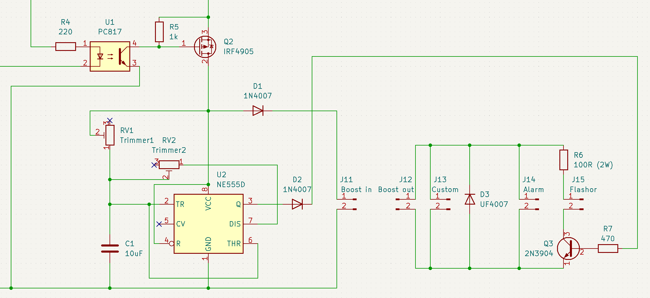
My new design:

 ()

On the left side of R4 there is an Arduino pin. On the source side of the IRF4905 is the main power source which is 9V. As you see I didn't leave anything to luck and I used an optocoupler and diodes to prevent any bad outcome. I am afraid of the 24V boost out (J12) killing my Arduino or 555 timer. The boost converter is an SX1308 module.

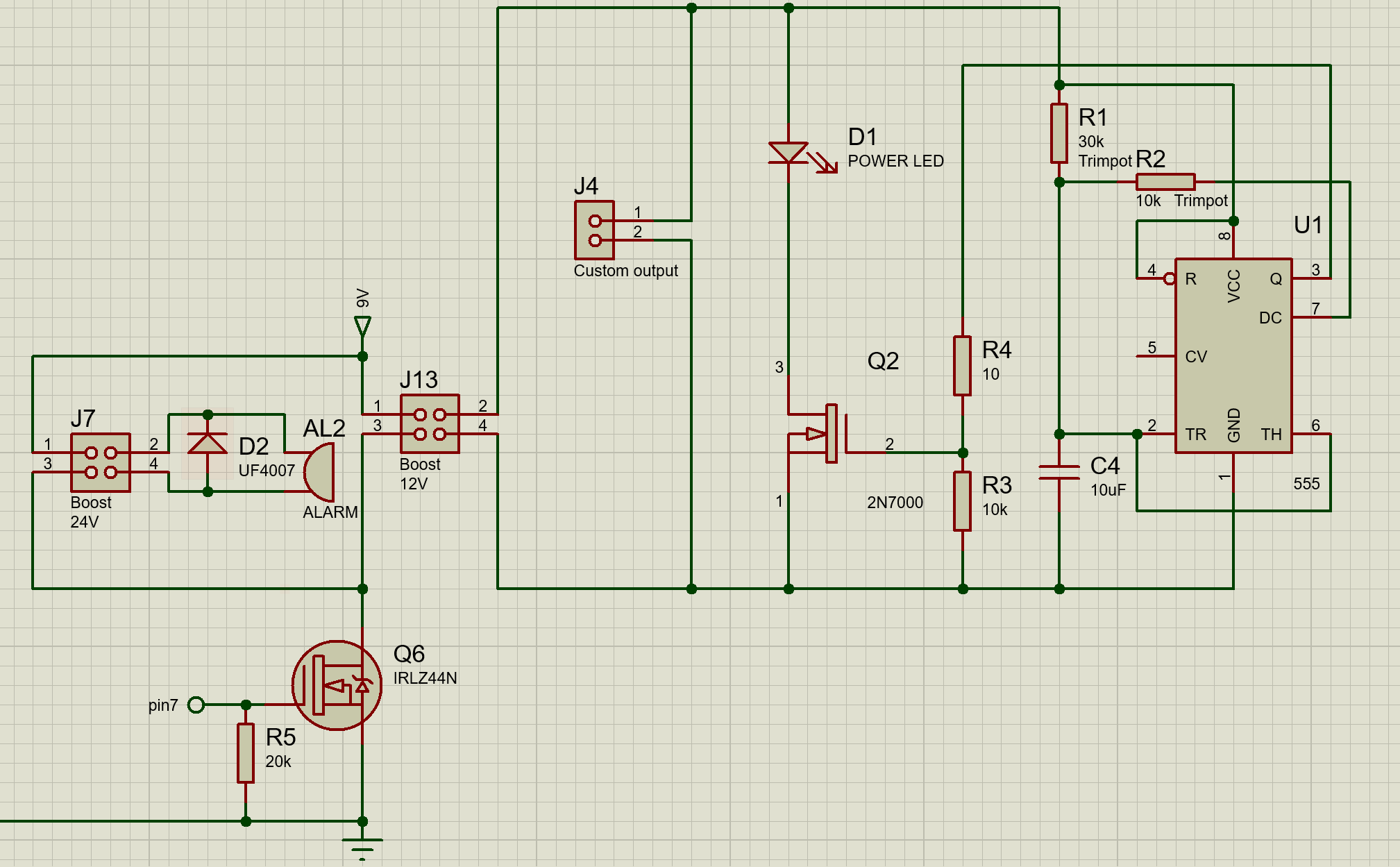
Back in the day I switched the whole timer and boost converter with a N-MOSFET from the gate (pin7 in the picture below) but somehow Arduino was burnt.

My old design:

burnt Arduino design

Several questions came to my mind about my new design:

  1. I think D1 and D2 are unnecessary. Can I remove them? They are to prevent any reverse current (as far as I know there shouldn't be any.)
  2. Is positive side switching is better than negative? I am using a P MOSFET here as you see.
  3. Can I use an NPN transistor instead of an optocoupler to pull the gate of the P MOSFET to zero volts? (Theoretically it must be yes.)

I am open to any advice for switching DC converters on and off. They have pins to turn on and off but I don't want any standby current when the system is battery operated. Also if I buy them as modules they don't have those pins.

\$\endgroup\$

1 Answer 1

3
\$\begingroup\$
  1. D1 and D2 are indeed unnecessary--I was going to ask what they were there for before reading the rest of your question.
  2. Whether there's a significant difference between high and low side switching is dependent on whether your step-up module is isolated or not. If it's isolated, there's no significant difference. If it's non-isolated, low-side switching is a bad idea, and you should switch the high side.
  3. Yes, you can pull the gate low with whatever you want to use. An optocoupler will provide isolation if used properly, but you aren't using it in a way that provides isolation anyway.

And the answer to the question in the title: The best and simplest way is to use the converter's EN or (¬)SHDN pin. Most DC-DC converters have such a pin, and driving it to the appropriate level (low for EN or ¬SHDN, high for ¬EN or SHDN) will disable the converter.

However, certain step-up topologies, including the basic boost converter, may not behave as you'd expect in this situation: turning off switching in such a topology will still leave the output connected (through a diode) to the input, so the input voltage will be applied to anything on the output. If your converter uses a flyback, forward, or SEPIC topology (or a few other less common ones like zeta or Ćuk), the output will fall to zero volts when the converter is shut down. Some standard boost controllers--but not all, or even most--also include a way to simply disconnect the output with a FET switch, avoiding this drawback of the simple converter.

\$\endgroup\$
4
  • \$\begingroup\$ I think the fact that there is a 0.2V voltage drop between the input and output of boost converter module shows that the module has basic non-isolated boost converter circuit as that drop is probably caused by a schottky diode. The diode also makes D1 absolutely unnecessary. Also input-output grounds are shorted so I am glad I used high side switching. There is already diodes between base and collector/emitter in the equivalent of BJTs so D2 is eliminated. I didn't know the optocoupler was not creating isolation, I will definatelly replace it a BJT, thanks. \$\endgroup\$ Commented Sep 18, 2022 at 23:46
  • \$\begingroup\$ I cant use shutdown pins because this is a module and I don't want standby current. And we know this is a basic topology, I am afraid about what you said about "input will be seen at the output" well when I switch with the MOSFET, the input will be zero volts isn't it? So this shouldn't be a problem? It would be disaster if output voltage was to be seen at the input but you didn't mention that I guess this won't happen. Can you open up the danger of "input voltage can be seen at the output" if there is no input voltage as in this case? \$\endgroup\$ Commented Sep 18, 2022 at 23:50
  • \$\begingroup\$ @CaveScientist If you need isolation, you can use an optocoupler for that. You've defeated the isolation by connecting the grounds on both sides, though. If you disconnect the input as you've said, there won't be anything at the output either. \$\endgroup\$
    – Hearth
    Commented Sep 19, 2022 at 0:06
  • \$\begingroup\$ Well that's the only ground in the circuit, there is no transformers. But the isolation is not a must, I was just too cautious because I burned an Arduino before. I replaced PC817 with BC548, I removed D1 and D2. Happy to hear no voltage will appear on the output when I turn off the P-MOS. I will build this and hope I won't burn another Arduino. Thanks. \$\endgroup\$ Commented Sep 19, 2022 at 0:23

Your Answer

By clicking “Post Your Answer”, you agree to our terms of service and acknowledge you have read our privacy policy.

Not the answer you're looking for? Browse other questions tagged or ask your own question.