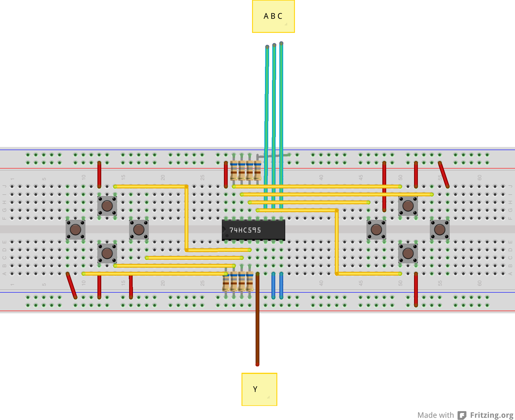
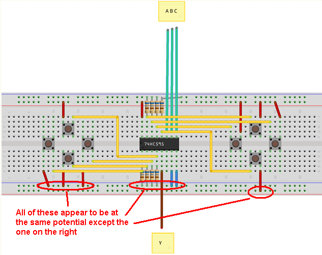
I'm trying to build a simple gamepad controller to learn more about multiplexers (in this case a SN74LS251. This is how I'm wiring it:

And this is the code I'm using to get the button states:
// Pins.
unsigned int y = 8;
unsigned int a = 9;
unsigned int b = 10;
unsigned int c = 11;

// Gamepad states.
unsigned int gamepad[2][4];

/**
 *  The usual Arduino setup.
 */
void setup() {
  // Set pin modes.
  pinMode(y, INPUT);
  pinMode(a, OUTPUT);
  pinMode(b, OUTPUT);
  pinMode(c, OUTPUT);

  // Set select pins LOW.
  digitalWrite(a, LOW);
  digitalWrite(b, LOW);
  digitalWrite(c, LOW);

  // Begin the Serial connection for debugging.
  Serial.begin(9600);
}

/**
 *  Set the select pins in the multiplexer.
 *
 *  @param a_stt Select pin A state.
 *  @param b_stt Select pin B state.
 *  @param c_stt Select pin C state.
 */
void multiplex_set(unsigned int a_stt, unsigned int b_stt, unsigned int c_stt) {
  digitalWrite(a, a_stt);
  digitalWrite(b, b_stt);
  digitalWrite(c, c_stt);
}

/**
 *  Get all the Gamepad states and put them into the result array.
 */
void get_gamepad_states() {
  // Left Gamepad.
  multiplex_set(LOW, LOW, LOW);
  gamepad[0][0] = digitalRead(y);
  multiplex_set(HIGH, LOW, LOW);
  gamepad[0][1] = digitalRead(y);
  multiplex_set(LOW, HIGH, LOW);
  gamepad[0][2] = digitalRead(y);
  multiplex_set(HIGH, HIGH, LOW);
  gamepad[0][3] = digitalRead(y);

  // Right Gamepad.
  multiplex_set(LOW, LOW, HIGH);
  gamepad[1][0] = digitalRead(y);
  multiplex_set(HIGH, LOW, HIGH);
  gamepad[1][1] = digitalRead(y);
  multiplex_set(LOW, HIGH, HIGH);
  gamepad[1][2] = digitalRead(y);
  multiplex_set(HIGH, HIGH, HIGH);
  gamepad[1][3] = digitalRead(y);
}

/**
 *  The usual Arduino loop.
 */
void loop() {
  get_gamepad_states();

  for (unsigned int i = 0; i < 2; i++) {
    if (i == 0) {
      Serial.println("LEFT");
    } else {
      Serial.println("RIGHT");
    }

    Serial.print("  Up: ");
    Serial.println(gamepad[i][0]);
    Serial.print("  Right: ");
    Serial.println(gamepad[i][1]);
    Serial.print("  Down: ");
    Serial.println(gamepad[i][2]);
    Serial.print("  Left: ");
    Serial.println(gamepad[i][3]);
    Serial.println("");
  }

  delay(500);
}
It was working last week when I tried it for the first time, but when I went to rebuild it today I started getting strange (and completely incorrect) readings like these (no buttons were pressed during this test and I still got some HIGHs for no reason):
LEFT
  Up: 0
  Right: 0
  Down: 0
  Left: 0

RIGHT
  Up: 0
  Right: 0
  Down: 0
  Left: 1

LEFT
  Up: 0
  Right: 0
  Down: 0
  Left: 0

RIGHT
  Up: 0
  Right: 0
  Down: 0
  Left: 0

LEFT
  Up: 0
  Right: 0
  Down: 0
  Left: 0

RIGHT
  Up: 0
  Right: 0
  Down: 0
  Left: 0
Also if I press a button nothing happens. Even if I put the Enable pin HIGH I'll still get the same pattern. What's wrong?

