1
\$\begingroup\$

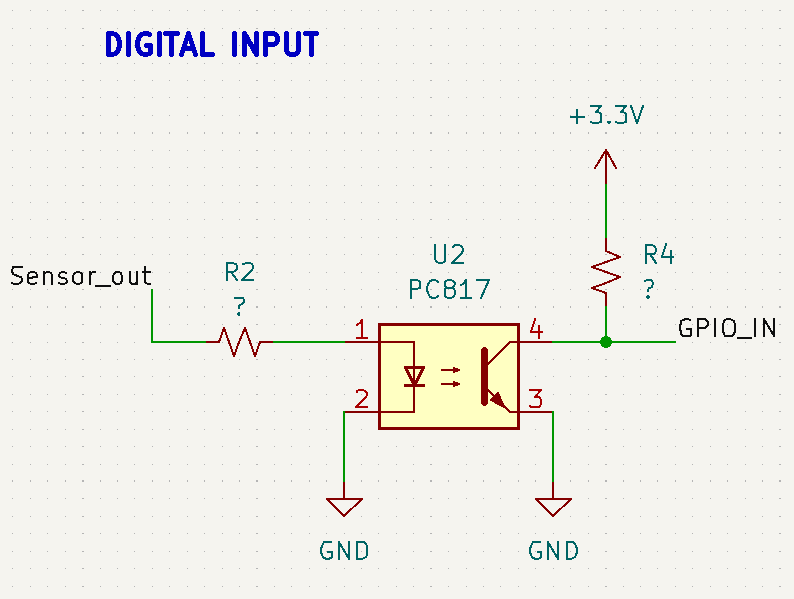
I am designing an I/O logic controller with multiple digital inputs. I am using an optocoupler(PC817) to provide isolation between sensor pulse output and microcontroller digital input(GPIO pin).
The sensor voltage is rated = 5vdc-24vdc
Microcontroller(STM32F401) supply Vcc=3.3v
Microcontroller GPIO input voltage=3.3v

enter image description here

I need help finding the appropriate value of resistors (both input and pull-up).

If I'm missing any protection or noise-filtering circuit, please et me know.

\$\endgroup\$
11
  • \$\begingroup\$ Your circuit indicates the the input is not isolated. \$\endgroup\$
    – Andy aka
    Commented Oct 12, 2022 at 13:45
  • 3
    \$\begingroup\$ But you have the same GND net connected on both sides of the optocoupler - so it's not isolated. \$\endgroup\$
    – brhans
    Commented Oct 12, 2022 at 16:21
  • 1
    \$\begingroup\$ Why do you need the optocoupler in the first place? \$\endgroup\$
    – Lundin
    Commented Oct 13, 2022 at 6:40
  • 1
    \$\begingroup\$ Well, doh... Why do you need isolation? \$\endgroup\$
    – Lundin
    Commented Oct 13, 2022 at 7:29
  • 1
    \$\begingroup\$ "because the sensor operating voltage is 5-24v" So what? Just do a plain voltage divider. "Both are from different sources" And you can't ground them together because...? \$\endgroup\$
    – Lundin
    Commented Oct 13, 2022 at 13:57

2 Answers 2

0
\$\begingroup\$

Manufacturers/suppliers of electronic components describe their products in datasheets. You can read UTMEL's (SHARP's) datasheet for PC817 optocoupler online.

Table Electro-optical Characteristics (page 4) specifies the photodiode current and forward voltage in the first row, where the column Parameter content is Forward Voltage. Photodiode voltage (values in columns MIN, TYP, MAX) is the voltage drop across the IR photodiode. This parameter is measured with the current through the photodiode as specified in column Conditions, \$I_F=20mA\$.

With these parameters, you can estimate the R2 value in the network SENSOR_OUT, R2, PC817 pin1 of your drawing. Take the typical forward voltage of 1.2V and the current of 20mA. This resistor is required if your sensor can sink current too great for your optocoupler and you should constrain the current to the values specified in the datasheet (\$I_F\$ MAX 50mA, typical 20mA).

If your sensor outputs a voltage signal of max 12V, you should select a resistor \$R_D\$ so that it provides a current of 20mA when the voltage across this resistor is 12V-1.2V=10.8V, so \$R_D\$=10.8V/20mA=540 Ohm. The calculated values are approximate values, you only have to guarantee that the currents/voltages are not violating Absolute Maximum Ratings (page 4) and at the same time the photodiode current is sufficient to safely turn the transistor on with IR light of the photodiode. If your signal is current and it is greater than 50mA, you can use a shunt to sink excessive current.
enter image description here

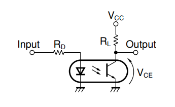
UTMEL's document PC817 Photocoupler Application, Pinout and Datasheet gives an example of using PC817, section How to use PC817, where the author uses \$R_L\$ = 1K to pull high the collector pin of the transistor. More advanced use of the optocoupler requires the designer to adjust the time parameters and frequency response, varying the pullup resistor value \$R_L\$, see page 8 of the datasheet, Figs 13-16.

Here I'm giving you only introductory instructions on selection of resistor values. More advanced designs would require adapting the circuit to detection of spike-shaped vs. continuous signal levels, optimizing the timing or frequency parameters and maybe other adjustments with other circuit components besides resistors.

\$\endgroup\$
1
  • \$\begingroup\$ Yes, the calculation part is done. Now I'm seeking help for any protection circuit if required. \$\endgroup\$
    – John Mist
    Commented Oct 13, 2022 at 5:13
1
\$\begingroup\$

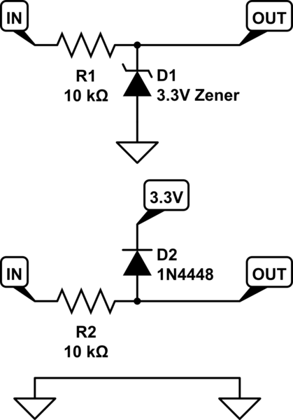
If you are only using the opto because the input voltage is higher, an opto is overkill. If you need an opto due to safety (unlikely with 24V) or noise, then just an opto is insufficient; You would need isolated or separate supplies and grounds too and isolation for all other signals crossing that power supply boundary.

schematic

simulate this circuit – Schematic created using CircuitLab

The main difference is the Zener clamps the voltage even when the 3.3V is unpowered which could be important if the pulse source can be powered while the 3.3V is unpowered. The Zener is slower and produces more heat in the diode, though heat is negligible due to the current limiting of the resistor.

The rail clamp diode can be faster if properly chosen (like a Schottky diode) with more flexible clamping voltage but needs 3.3V power.

\$\endgroup\$
10
  • \$\begingroup\$ Yes sir I understand your point. I've designed the ADC input using Zener clamp circuit. but in case of digital input I'm advised to use opto for isolation. So I need to calculate relevant parameters accordingly. \$\endgroup\$
    – John Mist
    Commented Oct 12, 2022 at 13:52
  • \$\begingroup\$ Then you need to isolate your power supplies and grounds too as well as all other signals, including that analog input or the opto is pointless. That is often more effort than it's worth. \$\endgroup\$
    – DKNguyen
    Commented Oct 12, 2022 at 13:55
  • 2
    \$\begingroup\$ A zener clamp is not a good idea for an ADC input! The zener starts conducting well before 3.3V is reached and will give you measurement errors. Use a two diode clamp circuit. For your opto, a 10k resistor should be adequate on the output side. For the input side, use ohms law to calc the value for around 5mA of led current. \$\endgroup\$
    – Kartman
    Commented Oct 12, 2022 at 14:53
  • \$\begingroup\$ Are these digital inputs or analog? (Using analog just for convenience..?) Zener is fine for digital of course. Opto is already useless for analog, at any kind of accuracy beyond just on-off. \$\endgroup\$ Commented Oct 12, 2022 at 18:07
  • \$\begingroup\$ Your second circuit won't work with GND as shown. OUT is connected to GND. \$\endgroup\$
    – PStechPaul
    Commented Oct 12, 2022 at 22:13

Your Answer

By clicking “Post Your Answer”, you agree to our terms of service and acknowledge you have read our privacy policy.

Not the answer you're looking for? Browse other questions tagged or ask your own question.