3
\$\begingroup\$

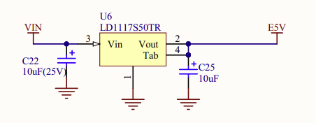
I will use this microcontroller board's voltage regulator(LD1117S50TR) with its datasheet here. And in my case VIN will be 12V:

enter image description here

Then E5V pin will power this ratio-metric sensor board(diagram) along with the uC board itself. If the 5V output of the regulator is not varying a lot with the input voltage variation or temperature, I'm planning to use only the output of the ratio-metric sensor not monitoring its Vcc(5V regulator output) for correction.

But I need roughly how to estimate the variation in 5V output if the input voltage(12V) varies 1V and temperature varies between 25°C and 55°C. (I guess the current sourced from the regulator matters but I'm not able to give an exact value at the moment so maybe take it 300mA)

\$\endgroup\$
1
  • \$\begingroup\$ Are you familiar with load and line regulation? \$\endgroup\$
    – Rahmany
    Commented Oct 14, 2022 at 8:48

2 Answers 2

4
\$\begingroup\$

The sensor datasheet says:

The sensor resistors are biased to the VCC supply voltage and produce a differential voltage that is ratiometric to VCC. This configuration is suited to applications where the A-to-D or other circuitry receiving the current sensor output signals are biased by and ratiometric to the same supply voltage as the current sensor.

Your sensor module includes an ADC which is also ratiometric. Sensor and ADC use the same VCC as reference, so you don't need to worry about VCC accuracy.

The sensor board has only 100nF capacitance on VCC, I'd add an electrolytic cap like 100µF and a resistor like 47R to the micro's VCC to filter out noise.

The ADC runs on 5V and its Vih is 0.7*5=3.5V and your micro runs on 3V3. So, if the micro's I2C pins are 5V tolerant (you should check) you should wire the I2C pullups to 5V. If they are not 5V tolerant, you will need an I2C voltage translator between the two. The usual schematic with two MOSFETs works fine.

\$\endgroup\$
2
\$\begingroup\$

VIN will be 12V

and

I guess the current sourced from the regulator matters but I'm not able to give an exact value at the moment so maybe take it 300mA

Worrying for a SOT223 5 volt linear regulator...

The LD1117S50TR is a SOT223 device and the data sheet specifies that it has a thermal resistance (junction to case) of 15°C/watt. But, the heat energy produced needs to be dissipated onto a large copper area and, if that was the top layer on a PCB having copper dimensions 50 mm x 50 mm, the extra thermal resistance to ambient would be approximately 38°C/watt. Figures taken from this calculator that I urge you to use to confirm what your likely value is.

I have just done a very quick calculation using the tool above so, it really is necessary for you to repeat this with more accurate figures that reproduces the copper size offered by the SOT223. However, I'm pretty sure you will be taken aback just how hot it will get.

  • If my figures are correct, the net thermal resistance from junction to ambient is 53°C/watt.

  • To produce an output of 300 mA, power dissipation will be 0.3 x (12 volts - 5 volts) = 2.1 watts

  • This means a temperature rise at the junction of 2.1 x 53° = 111.3°

  • In an ambient of 55° the junction would reach 166.3°

  • But the maximum junction temperature is only 125° for the device

  • And, localized heating raising the localized ambient temperature is not factored in yet

So, already I think you are in trouble (with a sizable 50 mm x 50 mm area of top copper) hence, I think it's not worth going further and calculating the other things until this is sorted out or abandoned.

\$\endgroup\$
11
  • \$\begingroup\$ If I can measure the current going into the VIN node, would that tell anything about the power dissipation of the regulator? 300mA my guess but now I want to estimate the real current. \$\endgroup\$
    – user1245
    Commented Oct 14, 2022 at 10:15
  • \$\begingroup\$ I measured that current as 85mA. But hard to measure access the Vout node \$\endgroup\$
    – user1245
    Commented Oct 14, 2022 at 10:22
  • \$\begingroup\$ Well, you said 300 mA originally and that provoked me to make my response. You are now armed with the method to evaluate the temperature for yourself @user1245 \$\endgroup\$
    – Andy aka
    Commented Oct 14, 2022 at 10:24
  • \$\begingroup\$ I see thank you but 85mA is the current going into the VIN pin. In your method you use output current of the regulator. Can I take it the same 85mA then? \$\endgroup\$
    – user1245
    Commented Oct 14, 2022 at 10:25
  • 1
    \$\begingroup\$ Look in the data sheet for the quiescent current however, it still goes into the regulator and warms it so I don't think it's that important to differentiate. \$\endgroup\$
    – Andy aka
    Commented Oct 14, 2022 at 10:27

Your Answer

By clicking “Post Your Answer”, you agree to our terms of service and acknowledge you have read our privacy policy.

Not the answer you're looking for? Browse other questions tagged or ask your own question.