4
\$\begingroup\$

I've got a solar PV inverter and grid feed supplying the house. They are both connected (via their respective circuit breakers) before the switchboard, so from the junction to the house switchboard it's only one wire.

How can the house consume the PV power first before the grid power? Let's say the house consumes 10 A. I would expect that the grid would supply 5 A and the PV inverter another 5 A, but no. The monitoring on the current probes shows that the PV delivers as much as it can to the house and only the deficit is supplied by the grid. If there's excess power generated from the PV it's exported to the grid - the current in the grid feed wire reverses and pushes power to the grid.

How is this possible? I would expect an equal supply from both sources.

Does the PV inverter generate a slightly higher voltage to override the grid supply, or is there some other trick?

\$\endgroup\$
7
  • \$\begingroup\$ Because it is AC, it's a bit more complicated, including a region where it draws from both, but you are on the right track with voltage; after all, in order to export to the grid, you must drive current into the grid (minding that it is AC and that means driving to a target voltage over time). \$\endgroup\$
    – Abel
    Commented Oct 18, 2022 at 1:52
  • \$\begingroup\$ @mkeith you say "the inverter pushes electricity out to the the grid" - how? With "Electricity" you probably mean current in this context - how does one push a current? The only way I can think of is generating a higher voltage than the grid to force the current flow to the lower voltage grid. Or is it something else? \$\endgroup\$
    – MLu
    Commented Oct 18, 2022 at 2:52
  • 1
    \$\begingroup\$ I have this kit from Texas Instruments. You can learn a great deal from it. Just FYI. It's not an end-to-end system. But many important details are there. Also go here. \$\endgroup\$
    – jonk
    Commented Oct 18, 2022 at 5:50
  • 1
    \$\begingroup\$ I don't have this one (yet), but here's another from Texas instruments to review. TI has a number of specialty goodies on this topic to help you understand things, in detail. \$\endgroup\$
    – jonk
    Commented Oct 18, 2022 at 5:58
  • \$\begingroup\$ @mkeith I think the question is about how the electricity from the inverter meets the electricity from the grid. I'm looking at the diagrams in jonk's very helpful docs and don't see where they meet! \$\endgroup\$
    – jonathanjo
    Commented Oct 18, 2022 at 5:59

6 Answers 6

2
\$\begingroup\$

How does a solar / PV inverter get preference over grid source for the house load?

Consider the following thought experiment. Suppose we have a circuit with an ideal voltage source, and ideal current source, and a resistive load, as in the following schematic.

schematic

simulate this circuit – Schematic created using CircuitLab

By Kirchhoff's Voltage Law (KVL), the voltage across Rload is equal to the voltage supplied by V1. The amount of current that I1 is capable of supplying has no bearing upon the voltage across Rload.

By Ohm's law, the current through Rload is

$$I_{load} = \frac{V_1}{R_{load}}$$

By Kirchhoff's Current Law (KCL) the current supplied by the voltage source + the current supplied by the current source, equals the current through the load. If the current supplied by the current source is less than the current drawn by the load, then current will flow out of the voltage source V1. That is, the voltage source will supply the deficit in current that the current source is unable to supply. If on the other hand, the current supplied by the current source is more than the current drawn by the load, then current will flow into the voltage source V1. In other words, the current source will "export" its surplus current to the voltage source. Note that V1, assuming it is a fixed voltage, has no "say" in how much current it supplies to the load (if any) nor whether it will receive "excess" current from the current source I1.

Now, in real life, the grid is not an ideal voltage source, but it can be, with some inaccuracies, approximated as an ideal voltage source. That is, the voltage supplied by the grid remains relatively constant despite changes in load current. Again, that is only an approximation.

Also, in real life, a grid-tie inverter is not an ideal current source, but if it is designed well, it behaves in a very similar way to the ideal current source in the thought experiment circuit.

I hope this thought experiment gives you intuition about how the grid-tie inverter is able to preferentially supply current to the load, and how excess current will be routed into the the grid. Now I am going to add some detail about the grid-tie inverter.

Although the details of the construction of an inverter will vary from model to model, a near universal feature will be an inductor (possibly "hidden" by a transformer) on the output side of the inverter. Over a small enough time frame, an inductor acts similar to an ideal current source. That is, it wants to output a specific current regardless of load. The amount of current actually changes with time, but over a short time-span, it can be treated as if the current is fixed. The rest of the grid-tie inverter is designed to control the current through the output inductor, through fast switching of a semiconductor. (The inverter is also designed to limit the voltage generated by the inductor in the case that grid power is lost -- one of the features of both an ideal current source and a real inductor is that if there is an insufficient sink for the current that the device wants to "push", the voltage can rise precipitously.)

This answer skips over many real world details, such as reactive power, which play a role in the power sharing between the grid and a grid-tie inverter. But hopefully, this answer gives you some intuition regarding how it is possible that the current drawn by a load may be preferentially supplied by a grid-tie inverter, rather than via the grid.

\$\endgroup\$
1
  • 1
    \$\begingroup\$ Thanks! Finally I understand what's going on in my PV system :) \$\endgroup\$
    – MLu
    Commented Oct 24, 2022 at 22:01
2
\$\begingroup\$

From what I read in the answers here and around the internet I came to a conclusion that the solar PV inverter works as a current source rather than voltage source. Since the current always flows from a higher potential to a lower potential the inverter is trying to pull up the AC output above the grid just enough to get rid of the power generated from the solar panels. It can't really effectively do anything to the grid voltage (there's no competing with the big power plants in the grid) but by trying to pull the voltage up it forces the current out.

Am I correct in this understanding?


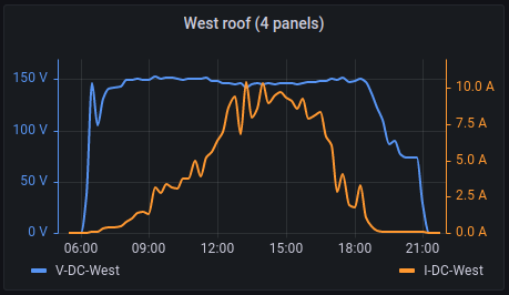
Interestingly on the DC side it's all about the current as well. The inverter MPPT units try to extract as much power from the panels as they can at all times and this is done by drawing variable current from the panels while keeping the voltage roughly constant at the maximum efficiency for the panels, as can be seen here:

MPPT - Vdc vs Idc

Not that it's related to what happens on the AC side but still found it interesting.

\$\endgroup\$
1
  • \$\begingroup\$ Yes. I think your understanding is correct. I mean, the actual control loops may not QUITE work the way you are saying, but the effect is that the input voltage is nearly constant and the input current varies. The AC output voltage is nearly constant, but the output current varies depending on how much power is available. \$\endgroup\$
    – user57037
    Commented Oct 21, 2022 at 2:52
1
\$\begingroup\$

The solar inverter has been designed to always put whatever it can produce into the grid, and the grid is stiff -- very stiff. The grid can sink all the energy you can produce and then some. The grid has capacity to sink maybe million times your power production.

If the solar inverter sees a low grid voltage of let's say 210 volts, it then raises this voltage as much as needed to dump all of the power it can produce into the grid. Let's say it produces 10 amperes, and the grid has a resistance of 1 ohm. In this case, the voltage will rise to 220 volts at the inverter.

If the solar inverter sees a high grid voltage of let's say 250 volts, it does the same.

Only when the grid voltage exceeds some sane limit, will the solar inverter stop production.

So if you draw a circuit of a solar inverter, a load and an AC source/sink, you will see that the current going to the load is sum of two currents: the current from solar inverter, and the current from the AC source/sink:

I_load = I_sourcesink + I_solar

You can modify this equation into:

I_sourcesink = I_load - I_solar

...in which case you have the deficit in the right side, and the current from the grid on the left side. You can see you will get from the grid only the current that you can't yourself produce. (However, three-phase systems are more complicated since you need to treat each phase separately, and it's possible you have overproduction on one phase and overconsumption on another.)

Currents are additive, but the solar inverter isn't an ideal constant current source. It is a (nearly) constant current source (or to be more accurate, constant power source) with some voltage limits set, so that if voltage rises above a certain threshold or falls below another threshold, production is stopped -- and automatically restarted, should the grid voltage stabilize.

Equal current from two supplies is only the case if the supplies both are constant-voltage supplies of exactly the same voltage, and their impedance is the same, or if the supplies have intelligent control designed for paralleling. This is usually very rare.

\$\endgroup\$
0
\$\begingroup\$

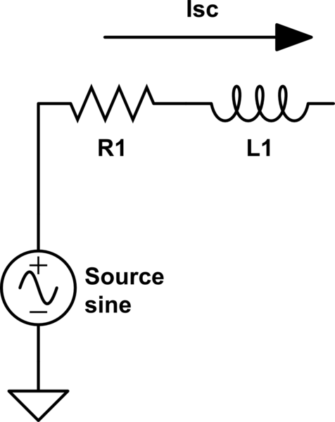
Your 2 sources each can be modeled by an ideal source with an "equivalent" impedance. Short-circuit current (Isc) ratings can be used to estimate the impedance using Ohm's Law => Z = V/Isc

schematic

simulate this circuit – Schematic created using CircuitLab

Your inverter likely has Isc listed, and if your power company will give you the Isc availability at your meter (commercial establishments often need the data to size their building's overcurrent protection systems, so they'll most likely get it to you - just maybe not as soon as you'd like), you'll see that the PV's Isc is higher, making it a "stronger" source.

\$\endgroup\$
0
\$\begingroup\$

How come that that house consumes the PV power first before the grid power?

Because while you are net importing, the solar power would not be able to get past the flow of imported power.

Let's say the house consumes 10 A. I would expect that the grid would supply 5 A and the PV inverter another 5 A, but no. The monitoring on the current probes shows that the PV delivers as much as it can to the house and only the deficit is supplied by the grid...

Except your service wires cannot handle both directions at once.

Here: Suppose you bought firewood and the guy across the street sold firewood. The next nearest supply is 50 miles away up a haul road that can only flow one way at a time for some reason. If your consumption exceeded your neighbor's production, you would absorb 100% of the latter and additional wood trucks would be coming toward you from the outside world. The road can't handle you importing while your neighbor exports.

And also, you don't want to export for 1 cent a KWH while you import for 18 cents a KWH. So bidirectional traffic would not be desired even if possible.

I'm sorry to explain it like you're 3, but it just isn't any complicateder than that. One way street.

\$\endgroup\$
0
\$\begingroup\$

Solar panels via the invertor are normally set to generate about 1.5V above the grid voltage when they are producing power. The consumer load will always take the slightly higher voltage first until that it is zero then it will make up the rest from the grid. Simple explanation for the way the power is used on my solar system!

(Simple electronics, if you join two separtate DC power sources together through diodes the one with the higher voltage will effectively block the lower one. This the way they work with ordinary meters. Smart meters are different!)

\$\endgroup\$

Your Answer

By clicking “Post Your Answer”, you agree to our terms of service and acknowledge you have read our privacy policy.

Not the answer you're looking for? Browse other questions tagged or ask your own question.