8
\$\begingroup\$

I really don't understand radio-frequency and how it works, and I get very confused on the theory and how an antenna etc. works. I first start with the electrical transformer. Energy is transferred through the magnetic field transferring the AC power to the LED without touching the wire. enter image description here

Then, the inductors loose a core and are moved farther apart. I still got the LED to light up at <2 Cm. enter image description here
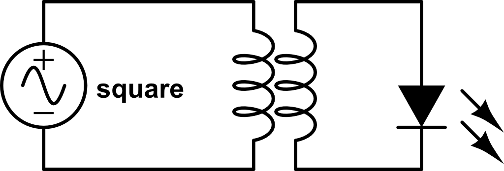
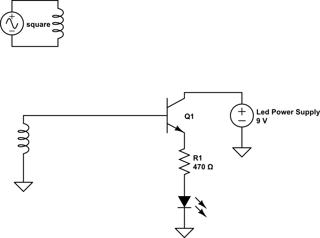
Last, Now, I want it even further. I know the energy can't travel too far, so I have to AMPLIFY it in some way. I amplify it in half-wave rectification (wouldn't need full for the LED anyway) and then I estimate the LED will turn on. I use a BJT. I think this will work but I am not sure and am not the expert in electronics. Is this RF? I understand the coil thing with electromagnets but why would an antenna be used because that is not a closed circuit and just one wire going in the air. Is it something to just expand the magnetic field and is it just attached to the inductor or something? Here is the circuit, again I don't know if it will work and I need advice. I just want it to be turning the led off or on depending if there is the AC voltage on or off. enter image description here
\$\endgroup\$

2 Answers 2

5
\$\begingroup\$

As Leon Heller said, this is not RF. However, it sure is an interesting experiment.

You have noticed that the magnetic field of the primary coil isn't strong enough to transfer energy over such a distance. Amplifying is a good idea indeed, but the question is: how much do you need to amplify?

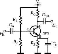
The transistor you're using in your circuit needs a specific voltage in order to start conducting. The secondary coil probably won't give such voltage. What you can do, is use the transistor as an amplifier:

enter image description here

As you can see, a pull-up (R1) and a pull-down (R2) are used to give the NPN transistor the minimum voltage it needs. With this circuit, even a tiny fluctuation in Vin will affect the current through collector and emitter. Vout is Vin, but amplified (and inverted, but that's not a problem here). You can use Vout to feed a transistor as a switch, as your circuit shows.

However, this is theory. How much you have to amplify heavily depends on the distance between the coils, and you might need to amplify so much, that it isn't worth trying.

Do you have an oscilloscope? I would recommend you making a graph of the amplitude of the voltage on the secondary coil as a function of the distance between the coils. I'm guessing here, but I think this will be an exponential function. When the voltage is nice AC, you might be able to do this with a multimeter as well. Now you have some data and you can calculate the amplification you need at a specific distance. The needed amplification will dramatically increase when increasing the distance, is my guess. That makes this setup not very useful on further distances, and that's why we use RF.


To get you started in RF, I can recommend you the book Crystal Sets to Sideband by Frank W. Harris, K0IYE. Skip or scan chapter one about the history of radio. Chapter 2 is basic knowledge which I think you already have, so also scan it. Chapter 3 is some blahblah about a workspace, which I found demotivating because Harris expects you to have a lot. In chapter 4, the fun starts, with a crystal set.

\$\endgroup\$
5
  • \$\begingroup\$ Which resistors are stable and should not change? \$\endgroup\$
    – skyler
    Commented Apr 1, 2013 at 21:30
  • \$\begingroup\$ @skyler I'm not sure what you mean. There are no variable resistors in the circuit. \$\endgroup\$
    – user17592
    Commented Apr 2, 2013 at 5:46
  • \$\begingroup\$ which resistors/caps do I know what the value are and which do I change depending on the amplification factor, because its kinda hard for me to add a lot of random components and expect it to work \$\endgroup\$
    – skyler
    Commented Apr 2, 2013 at 12:09
  • \$\begingroup\$ or what values do you reccomend to start with and for more amplification what should I change? \$\endgroup\$
    – skyler
    Commented Apr 2, 2013 at 12:10
  • \$\begingroup\$ @skyler set R1=R2 for base voltage about half of V+. Emitter voltage VE will about 0.6V less. Use data sheet, find max collector current, halve it. Select RE using R=E/I. If RC is too big, signal will clip. Capacitors effect minimum frequency (high pass filters). \$\endgroup\$ Commented Nov 16, 2014 at 3:03
4
\$\begingroup\$

That isn't RF. You are only dealing with magnetic fields whereas RF is electromagnetic radiation - both field components are required. Look up the experiments performed by Hertz if you want to see how radio was first demonstrated with very simple equipment.

The electromagnetic field produced by an antenna consists of an oscillating magnetic component surrounding the conductor, with an oscillating electric field along the conductor. It actually is a closed resonant circuit, because it is coupled capacitively to ground, or to the other conductor, in the case of a dipole.

\$\endgroup\$
1
  • \$\begingroup\$ When you have anything over DC, it is electromagnetic radiation though. How efficient of an antenna the coil is would be a different story, but an extremely small amount of the energy is transmitted into ELF EM radiation. \$\endgroup\$
    – skyler
    Commented Feb 13, 2015 at 13:46

Your Answer

By clicking “Post Your Answer”, you agree to our terms of service and acknowledge you have read our privacy policy.

Not the answer you're looking for? Browse other questions tagged or ask your own question.