2
\$\begingroup\$

I'm trying to make a blinking LED.

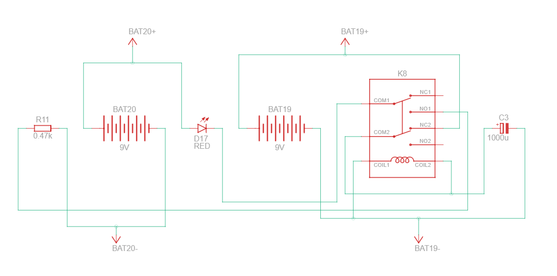
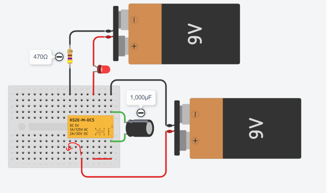
This circuit connects the two ends of a 9VDC battery through a DPDT relay. This turns on the switch which breaks the connection. When the connection breaks, it is turned on again, and the process repeats indefinitely.

I added a capacitor to slow down the oscillation, but my LED seems to be permanently on. What can I do to have it blink instead?

1

Link to Tinkercad of this circuit

Below is the auto-generated schematic. It's a bit messy and I'll try to clean it up if required, but I'm a complete beginner and it might take some time. :)

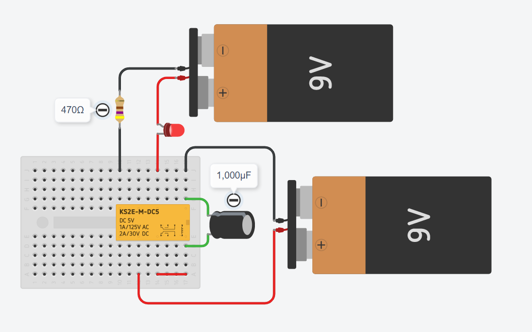
enter image description here

\$\endgroup\$
5
  • \$\begingroup\$ Do you hear any sound coming from the relay when the circuit is operating? \$\endgroup\$ Commented Oct 21, 2022 at 11:25
  • \$\begingroup\$ @Tanner, unfortunately I'm not doing this with real components. I'm using Tinkercad instead, and the relays do not give off sounds over there! \$\endgroup\$ Commented Oct 21, 2022 at 11:28
  • \$\begingroup\$ Please add a data sheet link for the relay. From what I can tell, it might not be suitable for use with a small 9 volt battery. \$\endgroup\$
    – Andy aka
    Commented Oct 21, 2022 at 11:44
  • \$\begingroup\$ Unfortunately, the software that I'm using doesn't provide any additional information beyond what's written on the component (I believe it's saying 5V coil voltage, which the battery should be good for). I think that the problem boils down to the software not allowing this type of circuit, might that be true? Btw, both received answers are correct. Which one should I Accept? \$\endgroup\$ Commented Oct 21, 2022 at 11:46
  • \$\begingroup\$ both received answers are correct. Which one should I Accept? You should wait for a bit longer in case a better-written answer comes along then accept the one that seems most suitable, accurate and clearest. Incidentally, better-written doesn't mean longer and more detailed - often, such answers can be worse as they're harder to wade through or see the points in. \$\endgroup\$
    – TonyM
    Commented Oct 21, 2022 at 12:12

2 Answers 2

1
\$\begingroup\$

You will need to wire the relay coil through the Normally Closed contact to have it buzz. So move the + wire as shown:

enter image description here

The idea is that the coil is energized intially, then the magnetic force opens the contacts and it drops out again (after the capacitor discharges). This is not very good for the relay contact- the capacitor charging current can exceed limits and it could weld, it would be a good idea to put a small resistor (maybe 10Ω) in series with the bottom battery or the capacitor, particularly if you are using alkaline batteries.

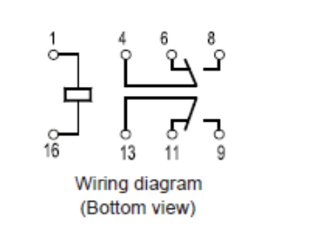
Edit: Actually the diagram on the relay appears to be incorrect according to the datasheet. So it should work as originally shown. Relays are shown in the de-energized state so pins 6, 11 are the N.C. contacts.

enter image description here

It is anybody's guess whether the simulation matches the image or the datasheet (or neither).

\$\endgroup\$
6
  • \$\begingroup\$ Hi, I tried to make the change (image), but it seems as if the LED is now permanently off. Maybe this is just an issue with the software itself? \$\endgroup\$ Commented Oct 21, 2022 at 11:38
  • \$\begingroup\$ Software? Oh, you're trying to do it in simulation. It may not work in simulation. \$\endgroup\$ Commented Oct 21, 2022 at 11:41
  • \$\begingroup\$ Haha, yeah... Unfortunately I'm not using real components. Okay then, it's probably the software. Thank you for the suggestion to add resistance to prevent welding. \$\endgroup\$ Commented Oct 21, 2022 at 11:42
  • 1
    \$\begingroup\$ Brilliant. I can't thank you enough for explaining it to me. Tinkercad changes the diagram on the relay while the simulation is running to show which pins are connected in the moment. I didn't clarify this and apologize. Thanks for explaining NO vs NC to me! \$\endgroup\$ Commented Oct 21, 2022 at 11:58
  • 1
    \$\begingroup\$ Hey @TarasLeskiv, this was (and still is) an issue with Tinkercad. I created a simple version on Falstad instead (link). It uses a SPDT instead as there is no DPDT in this sim (afaik). Otherwise I believe it's roughlyl the same. You can play around with the simulation / current speed (medium values are good for me). \$\endgroup\$ Commented Dec 28, 2023 at 18:46
0
\$\begingroup\$

It looks to me like the positive terminal of the lower battery is connected to the wrong terminal of the relay. It's connected to the NO terminal, and the coil is connected to the NC terminal, and this guarantees that the current will never make it from the battery to the coil.

If you connect the battery to the common terminal instead of the NO terminal, then your circuit seems like it should work.

\$\endgroup\$
1
  • \$\begingroup\$ Hi, I'm sorry, but I can't really tell the difference between the NO and NC terminal. Is this correct? :) \$\endgroup\$ Commented Oct 21, 2022 at 11:40

Your Answer

By clicking “Post Your Answer”, you agree to our terms of service and acknowledge you have read our privacy policy.

Not the answer you're looking for? Browse other questions tagged or ask your own question.