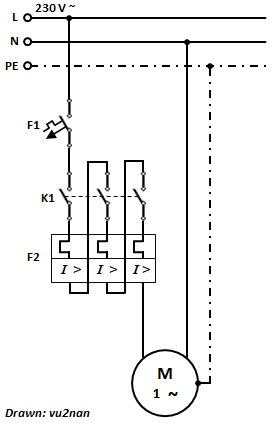
I am about to design a custom PCB that is supposed to switch a 230 V inductive motor with a 750 W rating over relays.
I have the "option" (since I happen to have them around) to do this using prebuilt relay circuit boards built for Arduino use, but honestly I find these to be quite concerning and flimsy and wouldn't trust these more than to switch low voltage low current loads for quick and dirty switching setups (like I do for a garage door opener I have modified to also work with 433 MHz remote inputs.) They are rated to work at 230 VAC at 10 A (at least the relay has it printed onto it, I find this to be an important difference) but I find the distance between the solder borders of the pins to be quite small with the bare minimum of 1.6mm which does not even get close to the minimum spacing of 2.5 mm that I calculate with the 325 V peak voltage +10% allowed mains variance.
Therefore I would like to do this on my own and integrate the relay circuit onto my PCB that is currently an ATtiny MCU operated over a 5 V line with a couple of port expanders and H-bridge drivers powering DC motors over a 12 V line.
I am aware about the design and safety guidelines outlined in IPC2221B and IPC9592B, trace widths and thicknesses, clearance and creepage distances and plan to outscale these by a couple of factors. The PCB under the relay will also have a slot milled to create an air gap between its 5 VDC and 230 VAC terminals. Furthermore, I would like to switch live and neutral using their own individual relays.
I have a couple of questions and assumptions I would have liked to have looked over, and in general, further input that I have missed so far.
I assume given the inductive load of the motor that regardless of the amperage rating of the relay I should use one certified for high inrush currents. Is that correct?
I plan on using logic level MOSFETs that I already have and am familiar with to drive the relays. I see on some occasions that people suggest optocouplers to switch relays on and off and advertise this choice with safety reasons. I don't see a benefit for that in my scenario here, as I am using the MOSFET to switch 5 VDC. Furthermore, are relays designed or should I expect them to fail in such a way that they will short their outputs with their logic inputs? In that case what good is an optocoupler going to do that is switching the relay on and off since the main 5 VDC will be shorted in either case? Is this something that is used for other switching scenarios?
What terminals should I use for the 230 VAC wires? The prebuilt Arduino relay boards use very garden-variety 2.54 mm pitch screw on terminals. I'm not at all happy with the distances there (1.6 mm between solder joints,) especially since I expect dust to get onto the board eventually, and they just look very brittle to me. Are there bigger higher pitch screw on terminals specifically for this design, or safe clamp-on solutions? (Even though I'm going to isolate everything exposed with hot glue.)
I noticed on all example schematics of the relays' datasheets that none of these have a current limiting resistor put in front of the coil of the relay. This seems to me to be a clear mistake and I am wondering why it is being left out in the schematics. Yes, the schematics referred to MOSFETs and not BJTs.
Other things I am missing?
I plan on ordering the parts along with other ones on my next Mouser order, so feel free to directly link to components on their site if you have any recommendations.

