There are problems with letting the user touch the PCB contacts directly.
A: ESD from the touch and environment is directly coupled into the circuit, so you'd need a couple of good TVS suppressors for high and low energy surges across the touch pad.
You'd also want to add some series resistance in the lines going to the active devices from the pads to absorb some of the remaining surge energy.
Adding shunt capacitance across the touch pads will also help dampen the surge voltage spike.
B: Moisture, dirt, skin oils, et. al. will contaminate the surface of the PCB and result in either intermittent "short circuit" events that look like touches when there are none, or open circuit events when there are touches because of oxidation and other surface contamination that is non conductive.
Although a reistive touch sensor as shown is cheap and simple, it isn't really greatly advantageous over using a domed / elastomeric switch which is the same sort of contact pad but with a conductive plate that is indirectly pressed down to bridge the contacts. The conductive top layer is handy in that it provides ESD isolation and also a place to put a legend to label the button, and it protects the PCB from contaminants making the repeatability and reliability of the touch contact better.
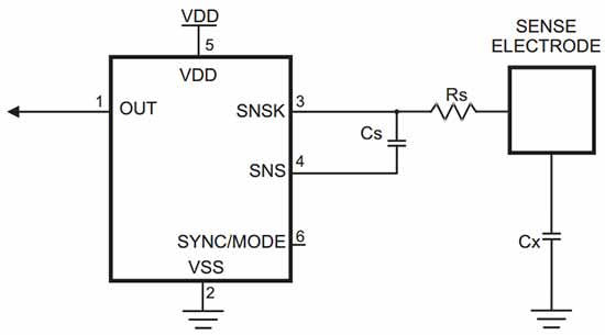
There are several "purpose built" capacitive touch sense detection ICs from Analog Devices, MICROCHIP, ATMEL, MAXIM, and others, and most inexpensive MCU lines such as the MSP430Gxxx, ATTiny, and others have a capacitive touch sense solution that is pretty much plug and play. Although using a MCU isn't necessarily the "simplest" solution, it may be the capacitive sensing solution that is the simplest one that is relatively predictable, reliable, configurable (how sensitive should it be? what to do when touch is detected?).
Another simple way to detect touch is to use a JFET with a floating gate to sense the electric charge and electrostatic field changes present when a finger is in proximity to the sensor or not. The sensitivity can be tuned by changing the pad size, the proximity and voltage level of the guard/bootstrap ring surrounding the pad, and by using some high impedance biasing. Search for JFET touch switch and JFET electrometer for circuit and part choices. A JFET input or CMOS op-amp can be made to perform similarly due to its high sensitivity and high impedance.
One way that is simple and relaible but not the lowest cost is simply to use a reflective or beam interruption type proximity switch device to sense when a finger is near or on the plane where the device is monitoring. If this is positioned behind a through hole on the PCB facing upward it can detect touch to the top copper surface.
So in short I think I agree that a resistive conductivity sensor may be one of the simpler approaches, you should also consider the aspects of senitivity tuning, reliability, and robustness. When those are considered you may want to add a cover layer to the PCB and ESD protection whether the resulting switch technology is resistive or capacitive at that point is your choice.
I like using the "PINOSC" feature of the MSP430Gxxx value line parts and their capacitive touch sense library, and there are similar solutions from ATMEL for some of their ATTiny parts since one has easy control of debouncing, sensitivity, adaptive threshold usage, et. al. Easier and more repeatable / dynamically auto-adjustable than tweaking things in analog.
http://www.ti.com/tool/capsenselibrary
http://www.ti.com/general/docs/lit/getliterature.tsp?baseLiteratureNumber=SLAA363&track=no
http://processors.wiki.ti.com/index.php/MSP430_Low_Cost_PinOsc_Capacitive_Touch_Overview
http://www.ti.com/430touch
http://www.eecs.berkeley.edu/~boser/courses/40/labs/docs/MSP430%20touch%20pad%20experiments.pdf
http://www.eecs.berkeley.edu/~boser/courses/40/labs/docs/MSP430%20touch%20pad%20slap105.pdf


