4
\$\begingroup\$

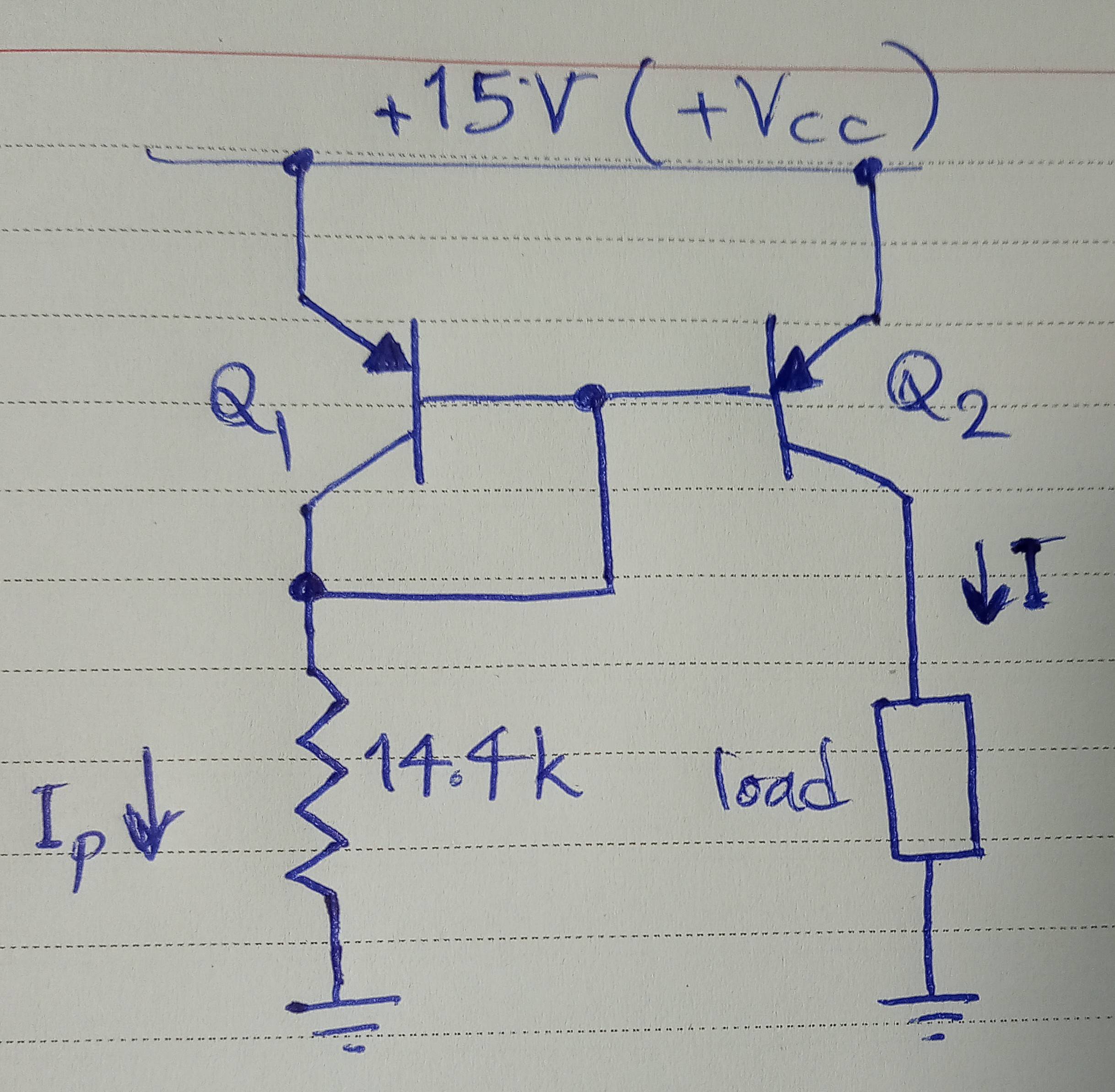
By "simple current mirror" I mean the following circuit.

enter image description here

Due to the Early effect the output current changes to some degree with output voltage. According to The Art of Electronics (3rd edition),

this is because of the slight variation of \$V_\text{BE}\$ with collector voltage at a given current in \$Q_2\$.

The way I understand the sentence above: Change in \$V_\text{CE}\$ at constant \$I_\text{C}\$ leads to change in \$V_\text{BE}\$, which, considering the Ebers-Moll equation, causes a change in \$I_\text{C}\$! By the way, the Ebers-Moll equation, according to the book, is \$I_\text{C}=I_\text{S}[\exp(V_\text{BE}/V_\text{T})-1]\$.

In the book, the Early effect is mathematically formulated for two cases: 1. Changes of \$V_\text{BE}\$ with \$V_\text{CE}\$ at constant \$I_\text{C}\$ 2. Changes of \$I_\text{C}\$ with \$V_\text{CE}\$ at constant \$V_\text{BE}\$. But in this circuit neither \$V_\text{BE}\$ nor \$I_\text{C}\$ is constant.

Another point: The two transistors have the same \$V_\text{BE}\$. So, applying Ebers-Moll equation, they must have the same \$I_\text{C}\$. The book says that output current can change as much as 25% due to change in output voltage. On the other hand, the current in the 14.4k resistor is almost constant (\$(15-0.6)/14.4\$). So about 25% of \$I_\text{C}\$ in Q1 must go to the bases via the wire connecting collector of Q1 to bases, which sounds strange.

\$\endgroup\$
8
  • \$\begingroup\$ I am sincerely impressed at your desire to understand what you are reading. I mean that. So +1. I'll write up something when I get a moment to help. There are some visual ways to see the Early effect. (There are some very good papers to read about it, too -- not the least by Dr. Early -- but they apply a relatively low-level physics model to explain the details and you may not need to get into all that right now. If you care about that, too, I'd be happy to include what I imagine I know about it. Say so, if so.) \$\endgroup\$
    – jonk
    Commented Nov 2, 2022 at 19:11
  • \$\begingroup\$ @jonk Thank you. It seems that the authors have tried to avoid math as much as possible. At some places I don't like it. For example, it is not clear how Ebers-Moll equation they give can be related to Early effect mathematically. I think the model we use for explaining a phenomenon should be as complicated as necessary, but no more. Even after Einstein we prefer to use Newtonian mechanics for cars on street. \$\endgroup\$
    – apadana
    Commented Nov 3, 2022 at 3:54
  • 2
    \$\begingroup\$ There are three successive versions of Ebers-Moll. The Level I is the DC model. The Level II includes AC capacitance. The Level III includes basewidth modulation (Early Effect.) There isn't a single Ebers-Moll. Following Ebers-Moll Level III is Gummel-Poon, which really changes things up a bit (closer to physics) and also enhances the basewidth modulation to also include the Late Effect. And there are many refinements to Gummel-Poon. The most recent is Mextram (which I think is nearing version 5.5 or something.) \$\endgroup\$
    – jonk
    Commented Nov 3, 2022 at 4:32
  • \$\begingroup\$ (The Ebers-Moll Level I model [DC] comes in three mathematically equivalent versions -- injection, transport, and hybrid- \$\pi\$. Only the hybrid- \$\pi\$ is usually carried forward into the Level II and III editions, though.) Do you want the description from Dr. Early? I have his paper and can explain it. Or do you just want to see how Ebers-Moll was modified to include it? \$\endgroup\$
    – jonk
    Commented Nov 3, 2022 at 4:33
  • 1
    \$\begingroup\$ Did you see this allaboutcircuits.com/technical-articles/… and this en.wikipedia.org/wiki/Early_effect \$\endgroup\$
    – G36
    Commented Nov 3, 2022 at 15:17

3 Answers 3

2
\$\begingroup\$

As I have come to understand it, the Early effect is about:

If VBE is held constant and VCB is increased then IC increases.

Alternatively, if IC is held constant and VCB is increased then VBE decreases.

In either of the above cases, when VCB is increased, beta (hFE) increases.

If the circuit is configured in a way that allows both VBE and IC to adjust their value then, when VCB increases, Early Effect is able to appear as a combination of both an increase in IC and a reduction in VBE & IB with a corresponding increase in beta (hFE).

That version of the Ebers–Moll which you have shown doesn't account for the Early effect. There is another factor added to the end of that simplified version of the Ebers–Moll equation to account for Early effect.

The multiplication factor is 1 + (VCE/VA) where VA is the Early voltage of the particular transistor. The Early voltage is typically lower in PNP transistors than in NPN transistors leading to greater Early Effect (larger increase in IC or reduction in VBE) for a given increase in VCB.

In your current mirror, there will be only a very small reduction in both VBE and in IB of Q2 as VCB is increased and almost all of the Early effect will show itself as an increase in IC. The relationship between VBE and IC of Q2 can be theoretically calculated using the extended version of the Ebers–Moll equation which includes the added factor to account for the Early effect.

In this situation, where VBE is held almost constant, the Early effect can be modeled by an added resistance placed between the collector and the emitter of Q2 which represents the output resistance at the collector of Q2 known as 1/hoe where hoe is the output conductance. Intuitively it can be seen that, when VBE is held constant, increasing VCB will draw more current through this resistance (RCE) resulting in an increase in IC.

Now if we were to add low value degeneration resistors into the emitter circuits of both Q1 & Q2 then, when we increase VCB, a good deal of the Early effect will happen as a reduction in VBE of Q2 (with the VBE of Q1 hardly changing). IC will still increase a little but far less than without the emitter degeneration resistors. So, by adding those resistors we have improved the performance of the current mirror which will have less variation in IC when the load varies and changes VCB.

\$\endgroup\$
3
  • \$\begingroup\$ @PeterMortensen Thanks for the edit Peter, that's added a professional looking touch to my answer. \$\endgroup\$
    – user173271
    Commented Nov 3, 2022 at 13:39
  • \$\begingroup\$ Thanks for the answer. In the last paragraph, you mean that when degeneration resistors are used Vce and Vbe of Q2 both change in a way that Ic remains almost constant? Do you know a place where I can find the calculations? \$\endgroup\$
    – apadana
    Commented Nov 4, 2022 at 7:12
  • \$\begingroup\$ @apadana Thanks for the acceptance vote. No sorry, I don't have a reference to a mathematical of analysis of that. \$\endgroup\$
    – user173271
    Commented Nov 4, 2022 at 7:56
4
\$\begingroup\$

The transistors are forced to have the same BE voltage, but can have different BC voltages, depending on the load.

The Early effect causes the collector currents to differ, despite the same BE voltages. The base current difference of Q2 will flow down the 14k resistor. This difference is rather small, because it is a 25% variation of Q2's base current that adds to Q1's collector current. So the resistor current will stay constant to ~1% or better usually.

\$\endgroup\$
2
\$\begingroup\$

The "slight variation of VBE with collector voltage at a given current in Q2" means that if collector voltage changes with fixed VBE then the collector current will change.

It's a roundabout way of putting it, but it's not wrong.

\$\endgroup\$

Your Answer

By clicking “Post Your Answer”, you agree to our terms of service and acknowledge you have read our privacy policy.

Not the answer you're looking for? Browse other questions tagged or ask your own question.