1
\$\begingroup\$

My question is regarding the question previously asked Only low-side output from MOSFET drivers is working.

I was able to get the IRS2108 MOSFET driver to work.

By working, I mean that I can measure the output of the MOSFET driver.

My question is regarding the expected waveform of the respective driver.

From my understanding the input to the MOSFET driver is essentially the same waveform. The output, however, is supposed to be inverted from one another with a deadtime of about 500 ns.

enter image description here

The image from the datasheet.

enter image description here

enter image description here

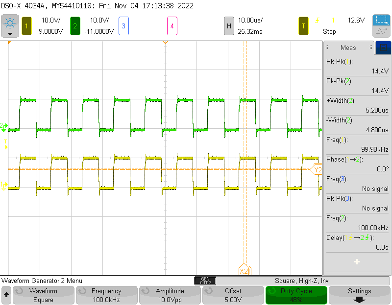
The above image is the output waveform I scoped from the HO and LO of the respective driver. Here the LO is exactly the same but with negative voltage introduced. Not sure why that is.

Yellow: LO; Green: HO

I tried inverting the inputs just to see what would happen, and I get the exact same output waveform from the driver. Any ideas as to why that is so and if I have understood the datasheet of the MOSFET correctly?

Edit 1: enter image description here

This is the waveform when I connected the rest of the components, i.e., the capacitor, inductor and the coil. Both the waves are positive, and no difference between the two.

Edit 2:

I replaced the right MOSFET driver IC as suggested by @Andyaka. I now receive the following waveform:

Yellow: LO Green: HO enter image description here

Although the alternating square waves can be visible, there is still a alot of noise. There is also a significant drop off in the HO signal, which i think is attributed to the Bootstrap Capacitor. I increased the switching frequency to 150kHz, and have capacitor value to aprrox. 400nF which should resonate with the coil(6.3µH) at 100kHz. From what I have read the resonant frequency should be less than the switching frequency of the MOSFETs. The main point I want to ask is whether the waveform I measured now is the correct one? Or Is there maybe some other components that need to be changed/calculated to get the optimum waveform. I get the same waveform as the Green wave indicated in the above image at the output connector. Should this be alternating at the output connector?

With the current output waveform, I still don't have any output from the Rx side. enter image description here
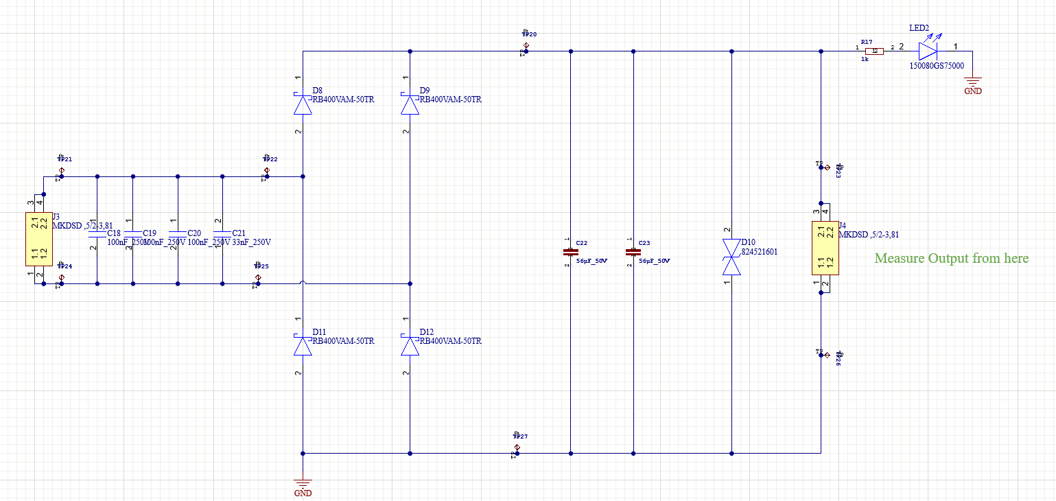
Coil : 7.5µH Cap: 330nF resonant frequency: 100kHz.

\$\endgroup\$
12
  • 2
    \$\begingroup\$ I'm wondering if the chip is damaged <-- where did you purchase it? \$\endgroup\$
    – Andy aka
    Commented Nov 4, 2022 at 13:52
  • \$\begingroup\$ In your 'scope capture, which output is correct? Then invert the phase of the other input. Assuming chips are good of course. \$\endgroup\$
    – rdtsc
    Commented Nov 4, 2022 at 13:53
  • \$\begingroup\$ @rdtsc, the green signal is the correct waveform, the yellow one is the one where i have the Negative signal. \$\endgroup\$ Commented Nov 4, 2022 at 13:54
  • \$\begingroup\$ @Andyaka, I think i got it from a local supplier, i don't exactly remember. It was a while ago. I have the similar output waveform from both chips. \$\endgroup\$ Commented Nov 4, 2022 at 13:56
  • 2
    \$\begingroup\$ Is this with differential probe for high side? Or +24V is unpowered? \$\endgroup\$ Commented Nov 4, 2022 at 14:03

2 Answers 2

1
\$\begingroup\$

It kind of just looks to me like your oscilloscope channels are inverted for some reason. At the top of your oscilloscope screen, you'll see:

1 10.0V/9.5000V 2 10.0V/-11.000V

This suggests to me that your circuit is actually working fine but for some reason, your scope is automatically inverting your channel.

\$\endgroup\$
1
  • \$\begingroup\$ Yes thank you, one of the probes were in fact inverted. good catch. I did not realize it. \$\endgroup\$ Commented Nov 9, 2022 at 12:42
0
\$\begingroup\$

I think, I messed up somewhere in my receiver circuit. When I made the receiver circuit on a breadboard, but instead of using the Diodes, I used a single phase rectifier bridge VS-1KAB-E, I also did not place the ESD diode and the two 56µH capacitors that are shown in the Rx schematic given above. I also replaced my voltage regulator on the Tx side, not sure whether that actually makes a difference to the circuit operation. The LED now glows faintly. I measured 18V at the resistor before the LED on the receiver end, but the current that is passing through is very minute.

\$\endgroup\$
6
  • \$\begingroup\$ Is there anyway to increase the current being transferred to the Rx end? \$\endgroup\$ Commented Nov 8, 2022 at 12:46
  • \$\begingroup\$ As per the other answer, was one of the scope probes inverted? Your original question has got nothing to do with your receiver circuit so, can you explain why you have accepted your own answer to a question that didn't seem to arise originally. This site does not look favourably on questions that move the goalposts so, maybe you can clear this up? \$\endgroup\$
    – Andy aka
    Commented Nov 9, 2022 at 12:14
  • \$\begingroup\$ Sorry about that, I got a little excited that it started to work, that I didn't clarify. The Image in Edit 2, is the Output waveform of the which I scoped at the transmitter end. Apparently this was the expected waveform which I didn't realize at the time. (Although improvements can and should be made). This led me to believe that my Transmitter circuit was finally working good enough to get some output at the Rx side. \$\endgroup\$ Commented Nov 9, 2022 at 12:34
  • \$\begingroup\$ The reason for posting the Rx circuit was, I didn't think there was anything wrong with it, So wanted to know if anyone had a better eye to identify the problem. But when I redid the RX circuit on a breadboard with the above mentioned setup the LED started to glow. I think when I get a new PCB with the updated schematics, I should have a better output, as breadboard causes a lot of stray capacitance and inductance. \$\endgroup\$ Commented Nov 9, 2022 at 12:46
  • \$\begingroup\$ You must not extend questions like this; keep to the original subject matter. This site showcases questions and answers and, your question has gone beyond what most would consider to be reasonable. Anyone reading this Q and A are likely to be very confused about why you have gone down this route. \$\endgroup\$
    – Andy aka
    Commented Nov 9, 2022 at 12:54

Your Answer

By clicking “Post Your Answer”, you agree to our terms of service and acknowledge you have read our privacy policy.

Not the answer you're looking for? Browse other questions tagged or ask your own question.