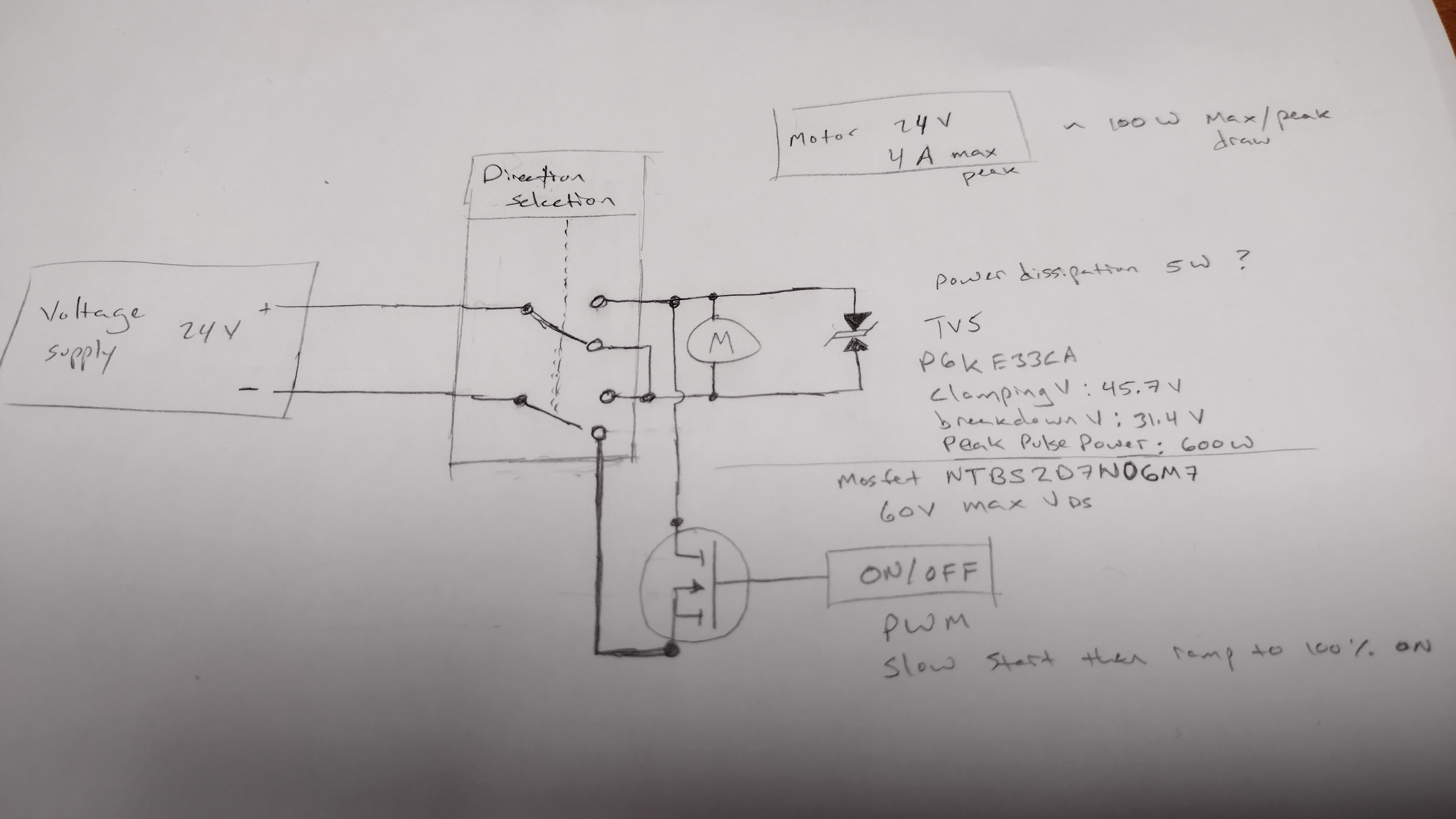
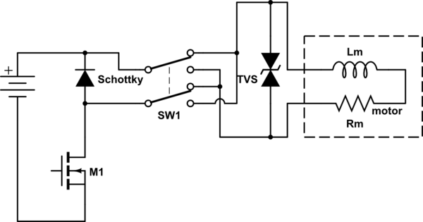
I am having an issue with a TVS diode failing short on 3 out of 7 units. The intended purpose of putting this diode across the motor leads was to protect the MOSFET and relay from the motor's back EMF.
The MOSFET is intended to turn off and on the motor as a low side switch. The MOSFET gate is receiving a PWM signal that is ramped to a 100% duty cycle for soft starting the motor.
The relay is intended to select the direction the motor is turning.
I believe the issue is that the TVS diode that was selected was not specced high enough for max. power dissipation. The PWM is creating thousands of instances where the TVS is conducting and eventually it becomes so hot it fails.
I was looking at back-to-back Zener diodes to use instead of the TVS, I don't know how I should spec those, as the power dissipation for most is not significantly higher than the current TVS diode's power dissipation rating.
Could I add a resistor in series with the TVS/back-to-back Zener diode to limit the power dissipation? Or is there a better way to protect the MOSFET and other components from the motor's back EMF?
Or I could select a different MOSFET which can withstand the back EMF seen on the drain of the MOSFET. The measured (with oscilloscope) back EMF of the motor seen on the MOSFET (drain to source) is 69 V without the TVS in the circuit. This perplexingly does not kill the MOSFET and it is still operating okay.
TVS currently used: P6KE33CA
MOSFET currently used: NTBS2D7N06M7
Picture of circuit:
Thanks for any insights.
Part 2:
After some testing and with some consideration and help from a few replies I have a much better looking waveform:
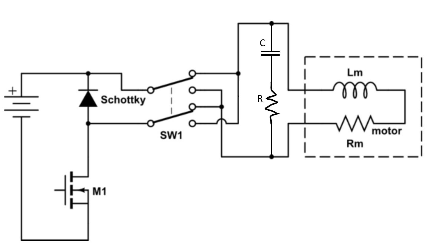
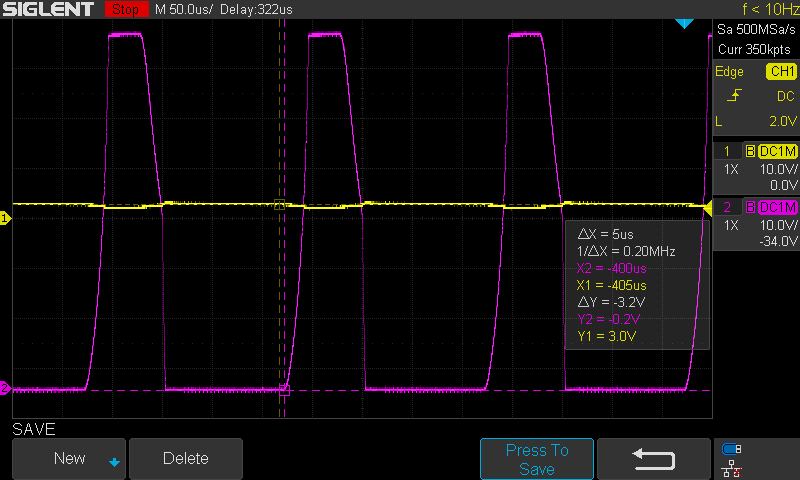
Changed the circuit for a Schottky diode to absorb the back EMF of the motor since I can now add the diode on the non motor side of the direction selecting relay. And experimented with values for an RC snubber across the motor leads and found that a .15uF cap with a 2 Ohm Resistor worked well.
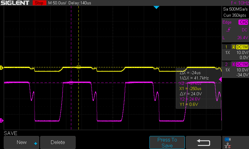
Oscilloscope pictures: Ch1 - Yellow - using differential probe across motor terminals with 1/10 attenuation (note might have polarity of probe reversed) Ch2 - Purple - Mosfet Drain to Source Voltage
PWM of motor without Schottky or snubber:
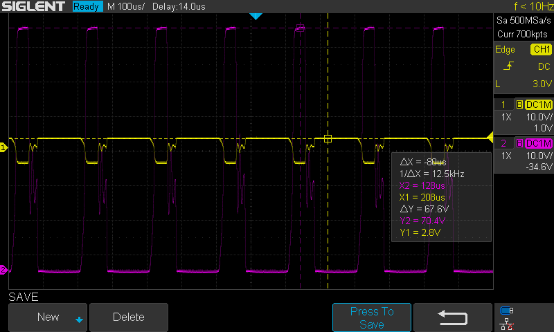 Zoomed in:
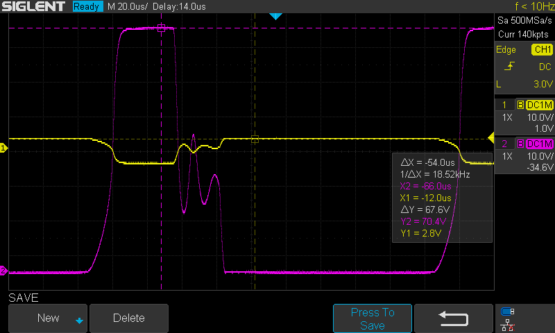
PWM of motor with Schottky, without snubber:
PWM of motor without Schottky, with snubber 0.15uF 2.0ohm:
PWM of motor with Schottky and with 0.15uF 2.0ohm snubber:
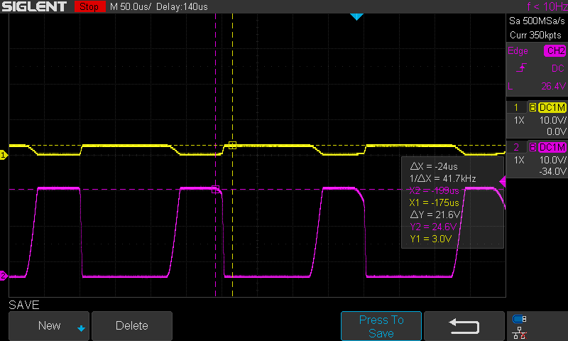
Summary: Having the Schottky diode on the opposite side of the direction selecting relay than the motor ensures the back emf of the motor is always in the forward direction of the Schottky. Spec'ing the Schottky for full motor amps and reverse standoff voltage of at least twice system voltage of 24V. Schottky protects the Mosfet as intended clamping the VDS of mosfet within safe operating conditions.
Having the Snubber helps smooth the ringing when the mosfet is turned off and on.
Thanks for all help and insight provided.

