0
\$\begingroup\$

I have the following circuit:
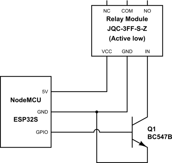
schematic

simulate this circuit – Schematic created using CircuitLab

When I digitalWrite(HIGH) the GPIO pin, the transistor closes and thus the relay's input is grounded, causing it to switch.

However on digitalWrite(LOW), the transistor opens, so the IN pin is floating, yet the relay switches.

I thought the operation was working on strokes of luck. But when I connect 5 V to pull it up like this, it won't switch when I make the GPIO pin high. I thought the connection to ground would cause it to be pulled down.
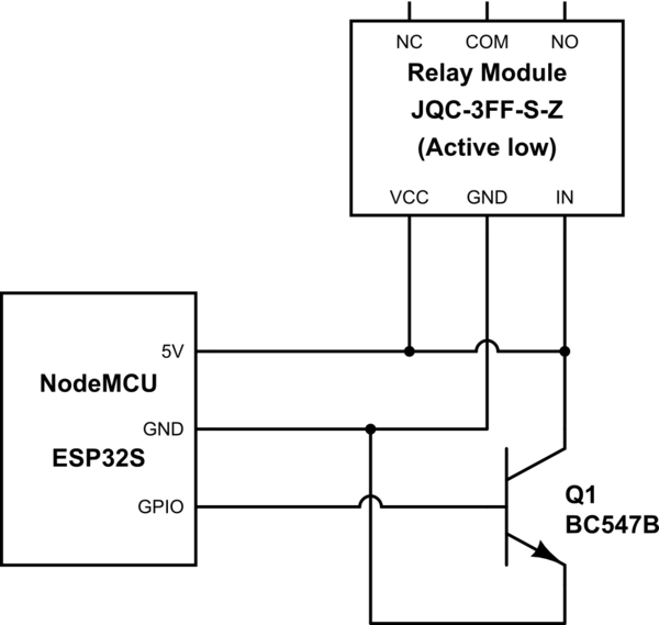
schematic

simulate this circuit

(The module looks like the one shown in this question.)

\$\endgroup\$
2
  • \$\begingroup\$ Where does the ground symbol connect to? It would be better and more obvious to draw the Q1 emitter with a wire to the nodemcu gnd pin. \$\endgroup\$
    – Kartman
    Commented Nov 16, 2022 at 22:07
  • \$\begingroup\$ @Kartman Yes indeed, I will fix it. \$\endgroup\$ Commented Nov 17, 2022 at 8:23

2 Answers 2

1
\$\begingroup\$

I found out why it is working.

For anyone encountering this, please read Justme's answer first.


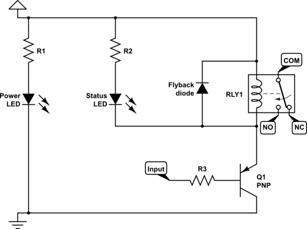
Here is a typical active-low trigger relay module circuit:

schematic

simulate this circuit – Schematic created using CircuitLab

When the input is floating, the base-collector junction in the PNP transistor, which would be forward biased, acts as a pull-up.

Thus, the relay switches.


In case of NPN, the base-emitter junction would be forward biased, and thus act as a pull-down.

Another way to understand it is this: leakage current from base to emitter will bring the base potential down to emitter potential, which is low. Hence, the transistor will be off. (Refer Neil_UK's answer to Transistor with floating base)

Base to emitter leakage current is encountered during any basic BJT device physics study. Emitter injection efficiency (γ) signifies that, since this leakage current is responsible for recombination in the emitter, reducing the efficiency.

\$\endgroup\$
0
\$\begingroup\$

You don't have a relay, you have a relay module with some other electronics as well in addition to the relay, and that part is unkown. So we don't know why it works like that. You need to show the schematics of the whole module before someone can say why it works like that.

But it does not matter as the problem may be elsewhere.

Your first schematic has an error that there is no base resistor on transistor. It may have damaged the MCU output pin or transistor.

The second schematic has even greater error. In addition to not having a base resistor, turning on the transistor will try to short circuit 5V to ground directly. The transistor may be damaged even more now.

So if the transistor is damaged it may not work correctly any more and can drive the relay module input to some state regardless of what the GPIO pin does. But the short circuit needs to be removed first.

\$\endgroup\$
3
  • \$\begingroup\$ Yeah I just realised and was editing the schematic. I have added more info (looks same like raspberrypi.stackexchange.com/q/73311). I purchased it off-the-shelf. \$\endgroup\$ Commented Nov 16, 2022 at 15:12
  • \$\begingroup\$ "But the short circuit needs to be removed first." Yes I had removed it. The transistor and MCU pins seem to be working fine as of now. Probably that's stroke of luck, ig... I will test them properly anyways. Thanks. \$\endgroup\$ Commented Nov 16, 2022 at 15:14
  • \$\begingroup\$ Why would the short circuit (which will damage xtor as you said, but ignoring it) not cause the IN pin to be pulled low, though? \$\endgroup\$ Commented Nov 17, 2022 at 9:13

Your Answer

By clicking “Post Your Answer”, you agree to our terms of service and acknowledge you have read our privacy policy.

Not the answer you're looking for? Browse other questions tagged or ask your own question.