0
\$\begingroup\$

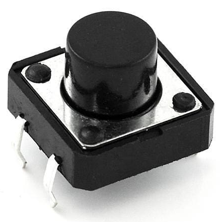
I've got a generic push button of the typical breadboard type (1/5" contact leg distance) like this one:

push button

As usual, it's attached to a +3.3 V lead with pull-up resistor, as well as GPIO and GND leads. On a breadboard I'd use the four elastic legs to attach the button. It will be used as a reset button and is therefore rather for "emergency" use.

Now I'd like to implant it into the front of my case, which will be equipped with a custom-made plastic front panel. Unfortunately, there is no PCB right behind the front panel (because there are other parts like keypad and display in the vicinity), just some case sheet metal. I can't find a ready-to-use connector I could then push into a drill hole in the sheet metal and secure it.

So: Is there a stable method to attach such a push button when you haven't got a PCB?

\$\endgroup\$
6
  • 2
    \$\begingroup\$ Why not get a panel-mount switch? \$\endgroup\$
    – John D
    Commented Nov 16, 2022 at 21:54
  • \$\begingroup\$ Do you actually mean a pull-down resistor? The switch shown is a PCB mount type; switches are not made to suit breadboards; breadboards are made to suit switches. \$\endgroup\$
    – Andy aka
    Commented Nov 16, 2022 at 21:56
  • \$\begingroup\$ A panel mount switch will also be more convenient since it has terminals that are designed for wires (or wire leads) instead of PC pins. \$\endgroup\$
    – vir
    Commented Nov 16, 2022 at 21:57
  • \$\begingroup\$ @Andyaka: No, it's really a pull-up resistor. And the switch is in fact a PCB type, but I pressed its legs (which are in fact springs) into the corresponding holes. And yes, a panel-mount button would be OK, save for the fact that there is not much space, and the button will be used to reset the system. \$\endgroup\$
    – Neppomuk
    Commented Nov 16, 2022 at 21:59
  • 7
    \$\begingroup\$ The EE answer to this question is "Source a switch which meets the requirement of being panel-mountable or use a PCB to mount the switch on which can then be mounted to the panel". Anything else is really just a hack. \$\endgroup\$
    – brhans
    Commented Nov 16, 2022 at 22:24

5 Answers 5

5
\$\begingroup\$

At the risk of being Captain Obvious: that's a board-mounted tactile switch, so it needs to be... mounted to a board. Which in turn mounts to your panel by some means (standoffs + screws, etc.) The board itself can be very cheap - it's typically a 1-layer board in most consumer electronics.

Otherwise, no reasonable panel-mount solution comes to mind that doesn't involve the equivalent of trapping the switch between the panel and some kind of solid piece fixed to the panel (hot glue doesn't count.)

But, you don't have to mount it on the panel, do you? If you can afford some plastic, the switch could be mounted to your main PCB and actuated indirectly by a lever / plunger from the front panel.

\$\endgroup\$
1
  • 1
    \$\begingroup\$ +1 for lever / plunger \$\endgroup\$
    – Mattman944
    Commented Nov 16, 2022 at 23:02
3
\$\begingroup\$

I doubt you'll find anything commercial that will fit. A small PCB, with a connector or wires, is the standard way to do this. The PCB can be mounted on molded bosses, for example.

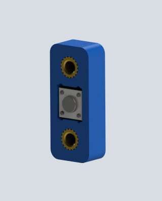
If you really insist, there's nothing stopping you from 3D printing a holder for the switch and fastening that to the back of the panel. You could then run wires with shrink tubing over the pins to a connector or directly solder to your board.

enter image description here

But a PCB will be inexpensive and rugged, and in my opinion, far preferred. .

\$\endgroup\$
2
  • \$\begingroup\$ Yep, the idea with the 1-layer PCB is at least not bad. The board would be very small, though, and I'd have to use screws and standoffs to fix it to the sheet metal underneath. I've already done a similar job on a (much larger) perfboard, so it shouldn't be too tricky. \$\endgroup\$
    – Neppomuk
    Commented Nov 17, 2022 at 22:09
  • \$\begingroup\$ I've done some commercial designs where the sub board is part of the main board and separated after assembly (and, in some cases, after initial testing) by snapping it off. \$\endgroup\$ Commented Nov 17, 2022 at 22:18
2
\$\begingroup\$

Commercial products often have a small PCB specifically for switches and indicator lights, mounted right behind the front panel. You could make one up out of a small piece of stripboard or perfboard.

\$\endgroup\$
1
\$\begingroup\$

Since it's an emergency reset button and rarely used and assuming there is a PCB below, just not close enough, you could mount it on the PCB and add a hole and tube to the case. This would allow someone to reset by pushing an unbent paper clip down the tube. If you want to be fancy, include a reset tool: a stiff rod on a handle.

\$\endgroup\$
0
\$\begingroup\$

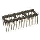
Solder it to some 0.1" headers or push it in to a 0.1" machine pin header socket. You can buy a 40 pin socket and use some snips to get the length you want.
enter image description here
Source: Jameco

\$\endgroup\$

Your Answer

By clicking “Post Your Answer”, you agree to our terms of service and acknowledge you have read our privacy policy.

Not the answer you're looking for? Browse other questions tagged or ask your own question.