3
\$\begingroup\$

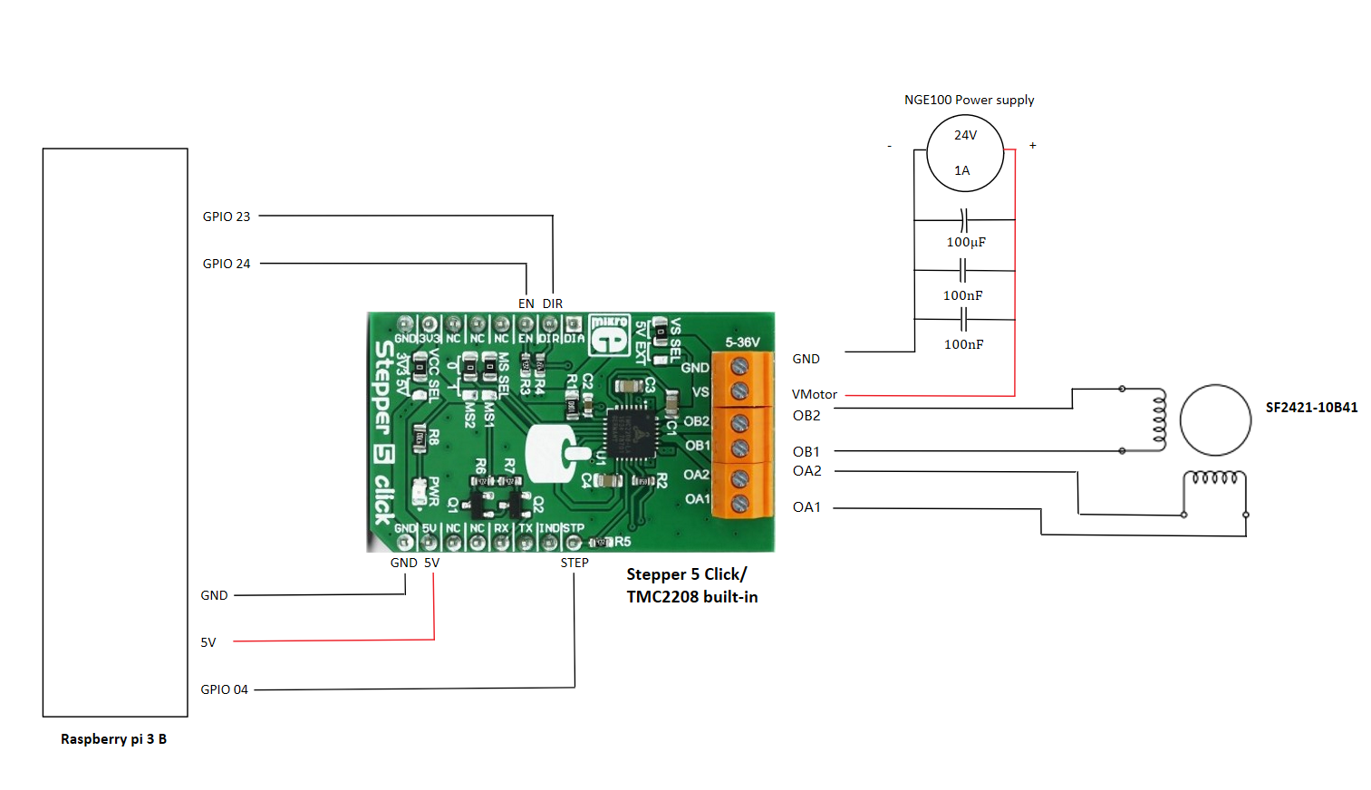
I recently purchased a SF2421-10B41 stepper motor and a Stepper 5 click board (TMC2208 driver IC built in) for my project, using Raspberry Pi 3B for programming, below is my sketch and the datasheet I found for the parts I used:

Sanyo Denki SF2421-10B41 Hybrid Stepper Motor

Stepper 5 click Board

TMC22xx Datasheet

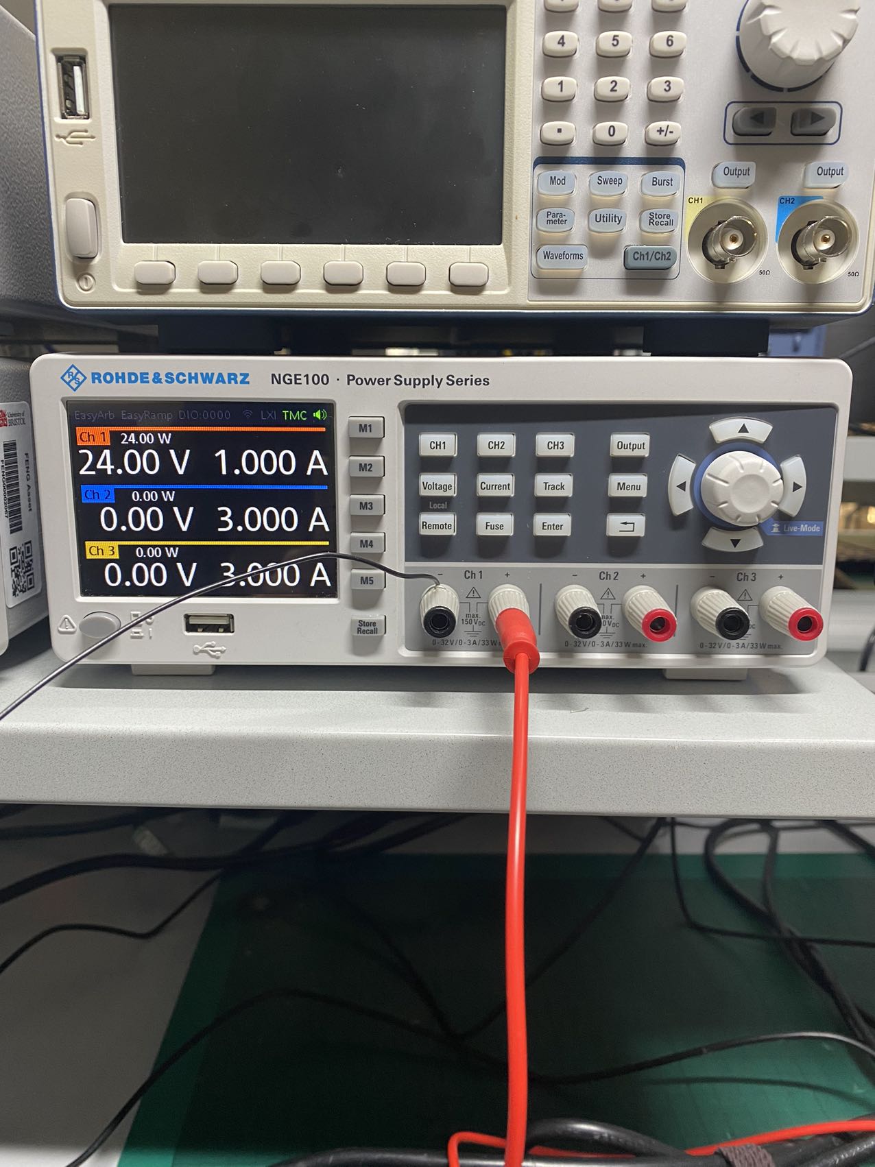
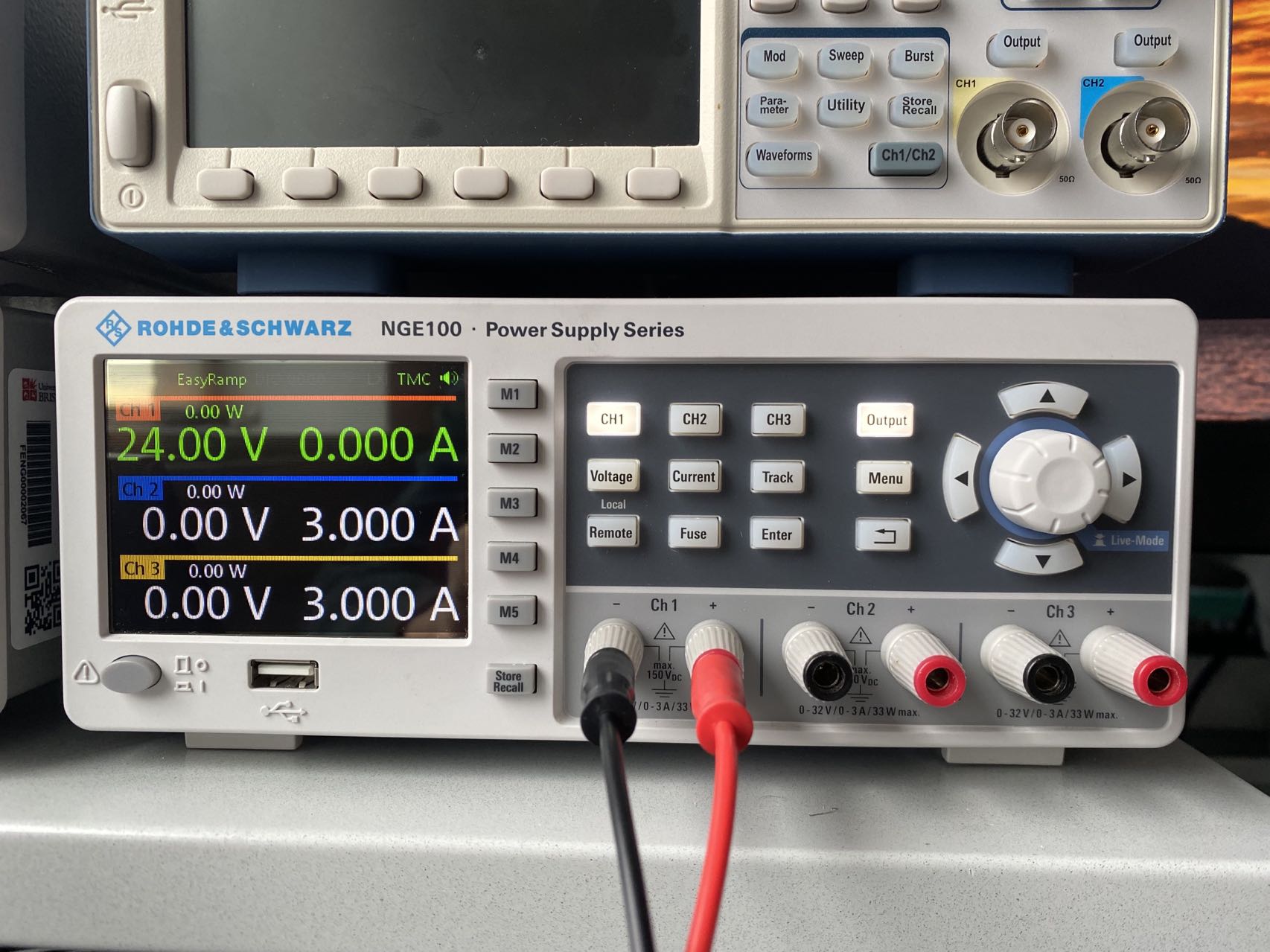
The motor power supply:

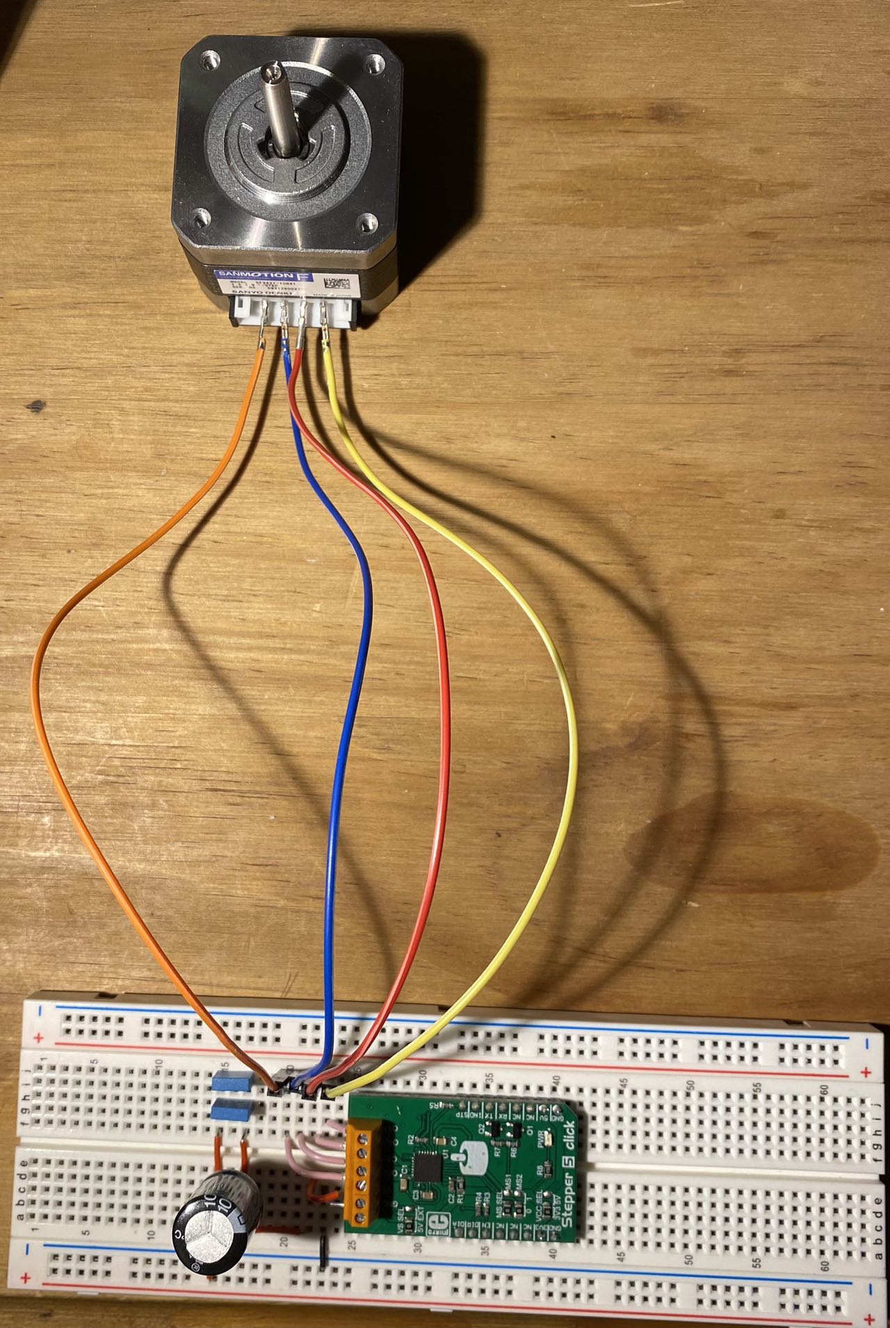
And the real connection is shown below:

Wires between click board and RPi are removed as they are exactly the same as in the schematic

Like I said in the title, my motor only gets vibration whenever I run my code in Thonny. I'll give some of the discoveries for the motor, and what I have done to fix my problem during my test:

The motor itself has 6 pins in total, I identified the 4 pins near the centre to be the two coil pairs(Orange-Blue; Red-Yellow), which has both winding resistance of 3.6Ω.

The 2 pins on the left and righthand side are the centre tap pins, but very strange is that, when I test the centre tap pin on the lefthand side with each of the 4 pins near the centre, I got no reading, this happened for the other centre tap as well. I said strange because there should be some resistance between them, I'm not sure if this means my motor is a broken one and not sure if this is the reason why my motor only vibrates and not turning.

What I've done so far:

  1. I've tried swapping the position between two coil pairs, that's a no use
  2. I've tried reversing the coils in both coil pairs, and swapping the position as well, those are no use as well
  3. increase the step delay (from 0.005s to 0.01s; 0.05s; 0.5s), I can feel the torque in all 4 cases, but that didn't help solving the problem

What I haven't done:

  1. Microstepping, I know that TMC2208 supports microstepping, but I don't know how to achieve this on this click board. The point is, the click board datasheet do gives the state for each MS pins for different step size, but the board itself doesn't has any physical MS pins, and so I don't know how to do the port mapping and therefore the coding.
  2. I suspect the motor itself is actually broken, so I'm planning to borrow another stepper motor from the university's lab, and see if is the motor's problem, or my problem.

Here is the two code files I got for my motor:

TMC2208.py

Import RPi.GPIO as GPIO
import time
import sys

class TMC2208(object):

    def __init__(self, DIR, STEP):

       self.DIR  = DIR
       self.STEP = STEP

       GPIO.setmode(GPIO.BCM)
       GPIO.setwarnings(False)

    def Run(self, clockwise=False, steps=200, stepdelay=.005, initdelay=.05):

       GPIO.setup(self.DIR,  GPIO.OUT)
       GPIO.setup(self.STEP, GPIO.OUT)

       GPIO.output(self.DIR, clockwise)

       try:
          for i in range(steps):
             GPIO.output(self.STEP, True)
             time.sleep(stepdelay)
             GPIO.output(self.STEP, False)
             time.sleep(stepdelay)

        finally:
           GPIO.output(self.STEP, False)
           GPIO.output(self.DIR,  False)

initDemo.py:

import TMC2208
import RPi.GPIO as GPIO
import time
import sys

direction = 23
step      = 4
EN        = 24

Xdirtest  = TMC2208.TMC2208(direction, step)
dir_array = [True, False]

GPIO.setup(EN, GPIO.OUT)
GPIO.output(EN, GPIO.LOW)

for i in range(2):
   Xdirtest.Run(dir_array[i%2], 200, .005, .05)
   time.sleep(1)

GPIO.cleanup()

I know this might a very basic problem, but here I am, stuck on this step. Any help or advices will be very appreciated, so much thanks!

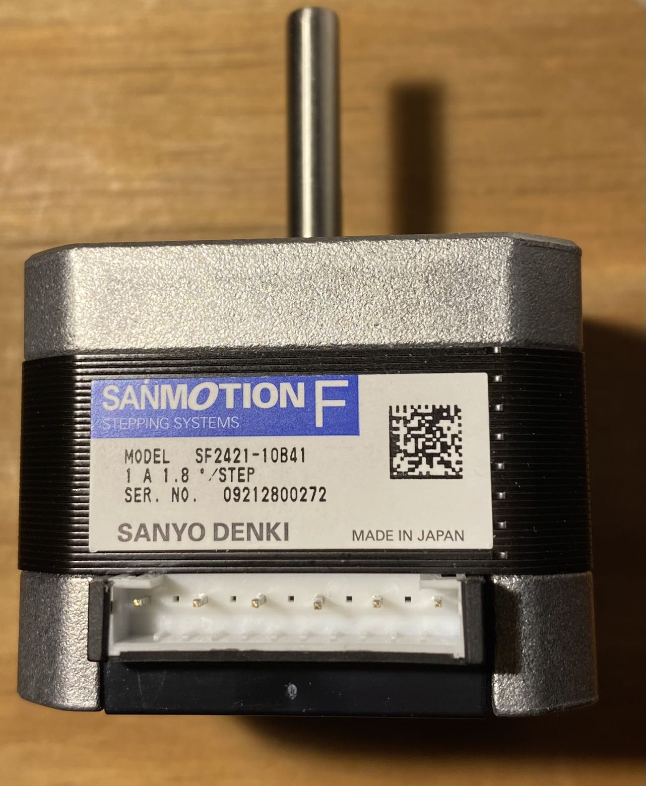
[UPDATE] Sticker on the motor:

[2022.12.07 UPDATE]

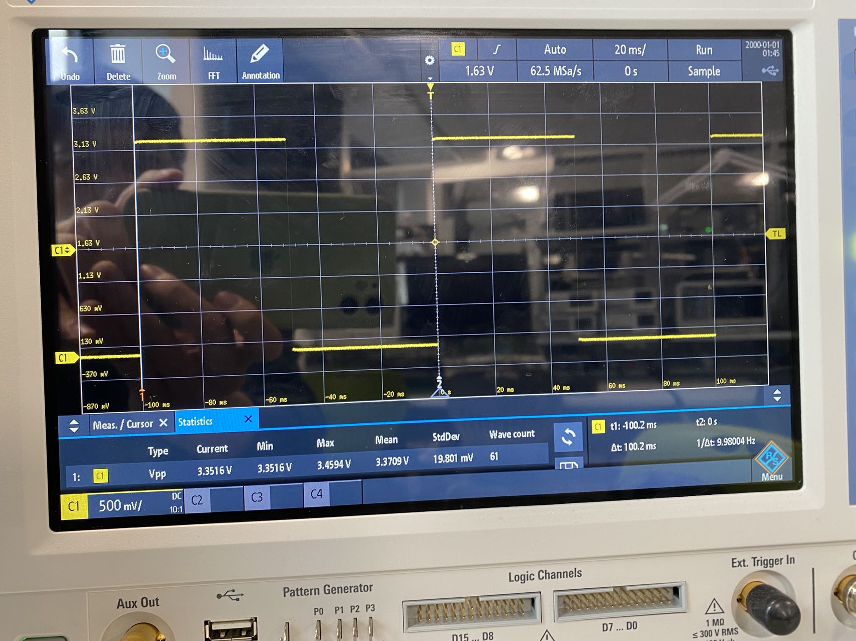
A pic for the STEP signal:

A pic for the current output:

So I got 0A current output when I turn on the power supply, but I can still read a correct STEP signal from my rpi board under this condition.

Another issue is that, when I test the output at OA1 and OA2 with oscilloscope, the voltage output just stays around 3.3V, it's not switching on and off to drive the motor. Right now, I'm considering to use a new driver and the one I chose is DRV8825.

\$\endgroup\$
10
  • 1
    \$\begingroup\$ Have you built a motion profile? You must move with acceleration, not immediately full speed \$\endgroup\$
    – TQQQ
    Commented Dec 6, 2022 at 23:55
  • \$\begingroup\$ the pinout you describe is not supported by the datasheet linked, can you get a clear shot of the motor nameplate/sticker so we can validate the wiring? \$\endgroup\$
    – Bryan
    Commented Dec 7, 2022 at 0:43
  • \$\begingroup\$ @Bryan I've add the sticker picture to my answer \$\endgroup\$
    – Yumo
    Commented Dec 7, 2022 at 0:49
  • 1
    \$\begingroup\$ It looks like the orange wire does not connect to the controller on the breadboard. \$\endgroup\$
    – PStechPaul
    Commented Dec 7, 2022 at 0:51
  • \$\begingroup\$ @TQQQ I haven't done that, our project is making a auto-maze solving system based on a 3d printer principle, so the motor itself actually will be moving at a relative low speed. \$\endgroup\$
    – Yumo
    Commented Dec 7, 2022 at 0:51

1 Answer 1

1
\$\begingroup\$

To systematically debug this.

  1. Measure resistance where you expect the coils to be (I would try right on the screws of the terminal block of the stepper driver, with power off)- in circuit. Each pair should measure less than 10Ω in either direction.

  2. If those are okay, ground the DIR and ENABLE inputs and test with a slow step input. 10Hz maybe. You have an oscilloscope so verify the frequency and voltage.

If both the above are nominal, maybe the stepper motor has an internal problem as you suspect. But you can do a bit more debugging by measuring the currents to the stepper coils with a multimeter and slowing the steps even further to read the actual currents and compare with expectations. The stepper can operate as slowly as you like, so a few seconds per step is fine.

Note. You have the stepper driver configured for 1/8 step. Changing that (1/2, 1/4, 1/16) is a matter of moving the MS1/MS2 0Ω jumpers from 0 to 1 as per the driver IC datasheet.

\$\endgroup\$
3
  • \$\begingroup\$ Hi, I just had a test with the points you mentioned, the coil pairs gave the same resistance as stated in the datasheet (3.6Ω for each coil pair, and around 3.9Ω~4.4Ω at the screw). The STEP signal works fairly as expected, the only concern is that its voltage level is 3.3V instead of 5V, I guess that's becase the click board has soldered the VCC SEL to 3.3V and I can't really physically change that. Right now I'm consider to use a DRV8825 so I can change those setting freely. \$\endgroup\$
    – Yumo
    Commented Dec 7, 2022 at 15:24
  • \$\begingroup\$ And for the current, a strange thing is that when I turn on the PS output, the current just drop to 0A, but I can still read a 3.3V STEP signal at STEP pin(I'll post the pic for that later). \$\endgroup\$
    – Yumo
    Commented Dec 7, 2022 at 15:32
  • \$\begingroup\$ How about using a function generator to supply the step input and eliminate the Pi entirely. (I'm not sure whether 3.3V or 5V is correct for your stepper driver in the current configuration.. but you should be). Just keep breaking down the problem until you find the cause. \$\endgroup\$ Commented Dec 7, 2022 at 15:57

Your Answer

By clicking “Post Your Answer”, you agree to our terms of service and acknowledge you have read our privacy policy.

Not the answer you're looking for? Browse other questions tagged or ask your own question.