6
\$\begingroup\$

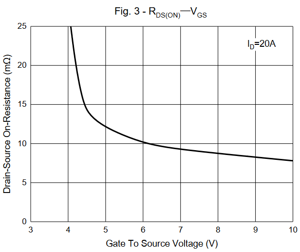
I am working on an application where a nMOS is switched at few hundred kHz in a buck DC-DC with its Vds max of 60V. I have the option to choose the gate drive voltage. Its one of the usual power MOSFET with rating of Vgs max of ±20V and the Vgs vs Rds-ON is as shown below.

enter image description here

The graph shows that the Rds-ON is decreasing with higher Vgs although it ends at 10V and also there is a diminishing return in reduction of Rds-ON. Would higher gate-source voltage lead to higher switching loss?

Overall, in this scenario to optimize for lower conduction and switching power loss, what would be the optimal gate voltage to use?

\$\endgroup\$
1
  • 2
    \$\begingroup\$ Consider the gate charge and switching frequency as well. It's not trivial to get an optimal solution; I usually just go for a good enough solution. \$\endgroup\$
    – Hearth
    Commented Dec 9, 2022 at 3:48

3 Answers 3

6
\$\begingroup\$

There are three things to consider:

  1. Conduction loss. As noted, higher VGS(on) reduces this, albeit incrementally past a point, which also depends on ID with respect to overall device ratings.
  2. Gate drive loss. Normally a small part of the overall total, but as it's often localized to a small gate driver or controller IC, and maybe a resistor or two, dissipating a few watts here could be quite problematic.
  3. Switching loss. This is a more subtle effect, but consider this: the bulk of the switching process (commutation) occurs over a narrow band of gate voltage: the Miller plateau. The amount of current sourced/sunk to the gate during that phase, determines the duration of this feature. The plateau voltage also depends on ID and VGS(th) (increasing with both), and is further modified by source-terminal impedance (especially inductance, raising it during turn-on and lowering it during turn-off).

Fast switching requires a large voltage drop across the gate drive circuit resistances. This is easier achieved with higher VGS(th) and higher VGS(on). Therefore, this is a big concern when using "logic level" types (typically VGS(th) in the 0.8-2V range), for example.

This effect is directly observable in datasheets, when switching times are given. Turn-off is slower than turn-on because the plateau is generally below half VGS(on).

There are even cases where negative VGS(off) is desirable. This draws more current through the total gate resistance, speeding turn-off; it also provides insurance against dV/dt induced turn-on (i.e., a sudden change in VDS drives charge into CGD and CGS, changing VGS).

There are many transistor types, load conditions and optimization goals to choose from, so the most general advice I can offer is: try different values and see what works best.

Most likely, drive around 8-15V will suffice, and losses can be better controlled by adjusting gate resistance (including using a diode to get asymmetrical rise/fall), timing (if applicable), strays in the switching loop, and other components (like inductor and capacitor losses). Not to mention synchronous rectification.

\$\endgroup\$
3
\$\begingroup\$

An optimal solution can only be found for a single load condition. Usually MOSFETs are driven at the Vgs provided in the datasheet to minimize Rds since maximum load current is the thermally critical operating point. 10V would be a very common drive voltage for a discrete Si-MOSFET. If you can get away with a much smaller Vgs (higher Rds) at full load, you might as well reconsider your MOSFET choice and look for one with lower Qg and higher Rds. On the other hand you have to keep driver losses within reasonable margins to not thermally overload the driver chip.

\$\endgroup\$
2
\$\begingroup\$

More gate drive will reduce conduction losses due to RDs on decreases.Gate switching losses will go up because of energy in gate source capacitance not being recovered and being wastes in internal gate resistance ,External gate resistance ,and the driver chip.A current dependant gate voltage scheme would be best .Maybe 6v at low current and say 15V at high current .Do your homework ,the curve you provided is just for 20Amp .There is a family of curves for different currents .

\$\endgroup\$
2
  • \$\begingroup\$ I understand that there will be higher loss in the gate driver and gate series resistance with higher Vgs. How does this translate to switching loss in the MOSFET? Also I don't have option of variable Vgs, so how to get to optimal value? \$\endgroup\$
    – EarthLord
    Commented Dec 9, 2022 at 4:50
  • \$\begingroup\$ @EarthLord As a 1st level estimate, power dissipation in a FET is just the integral of Vds times Id divided by the time period. The Vgs swing impacts the dissipation of whatever is driving the gate. But not the FET itself (except as already noted.) \$\endgroup\$
    – jonk
    Commented Dec 9, 2022 at 5:00

Your Answer

By clicking “Post Your Answer”, you agree to our terms of service and acknowledge you have read our privacy policy.

Not the answer you're looking for? Browse other questions tagged or ask your own question.