20
\$\begingroup\$

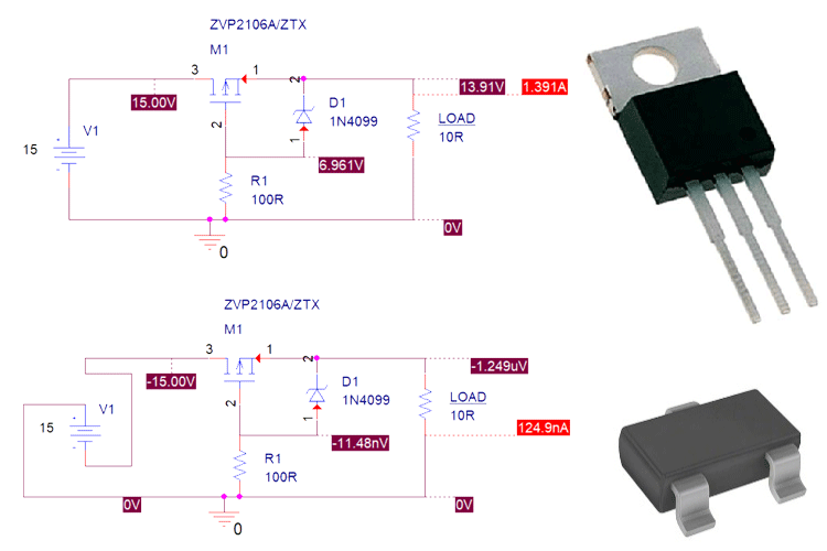
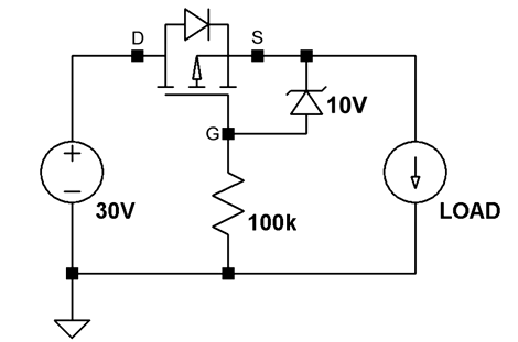
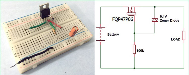
I've been looking into reverse polarity protection and come across a lot of resources that recommend using a P-channel MOSFET with a Zener diode.

Every single one of these circuits shows the MOSFET reversed - as if current was flowing from drain->source, when in reality the current in P-FETs flows from source->drain.

Some of the articles even have a comment that echoes my confusion. Am I actually missing something here or is there some reason why all of these circuits seem incorrect?

A few examples:

enter image description here

enter image description here

enter image description here

If these circuits are wrong, then I assume it's more than just the MOSFET being reversed, and the Zener diode should still be between the source and gate. Is that correct?

\$\endgroup\$

2 Answers 2

29
\$\begingroup\$

This circuit looks odd the first time you see it. When a MOSFET (P or N-channel) is on it conducts in both directions.

But, in order for a discrete MOSFET to block current, the body diode must be reverse-biased. The circuits you linked to are correct. When the power supply is connected properly, the MOSFET will be held on and will conduct with low resistance.

If the MOSFET in one of those circuits were to be reversed, it would still work in the forward direction. But then in reverse polarity, even though the MOSFET would be biased "off" by gate voltage, the body diode would be forward biased. So the MOSFET would conduct via the body diode and the main purpose of the circuit would be defeated.

\$\endgroup\$
7
  • 4
    \$\begingroup\$ Exactly- The point is that when the polarity is correct, the channel conducts and shorts out the body diode, so you don't have the large voltage drop and power dissipation you would if you just used a diode. When the applied voltage is the wrong polarity, the channel remains off and the body diode is reverse biased preventing current flow. \$\endgroup\$
    – John D
    Commented Dec 19, 2022 at 23:12
  • 2
    \$\begingroup\$ FETs (not only MOSFETs) are in fact pretty much symmetric devices. Some of them have the body exposed as a 4th terminal (instead of connecting it internally to the source) and their source and drain are interchangeable for almost any purpose. \$\endgroup\$
    – fraxinus
    Commented Dec 20, 2022 at 10:07
  • 3
    \$\begingroup\$ The only 4-terminal transistors I have seen were not power FETs in the first place. There probably is some practical limitation for making them. \$\endgroup\$
    – fraxinus
    Commented Dec 20, 2022 at 17:46
  • 2
    \$\begingroup\$ Yes. The circuit is quite odd the first time you see it. I remember being perplexed by it too. I had to draw it a few different ways and think about it quite a bit. But that was a long time ago for me. So the question is very understandable. \$\endgroup\$
    – user57037
    Commented Dec 20, 2022 at 18:43
  • 7
    \$\begingroup\$ As a side note, I personally always prefer to use MOSFET symbols with the body diode shown explicitly. It helps me maintain my sanity when analyzing these circuits. If the body diode is not shown, it is too easy to forget about it. \$\endgroup\$
    – user57037
    Commented Dec 20, 2022 at 18:54
10
\$\begingroup\$

In reality, MOSFETs conduct in either direction. In these circuits it has to be connected in this direction in order for the body diode to be able to block reverse polarity voltage

\$\endgroup\$
1
  • 1
    \$\begingroup\$ mkeith had a more complete answer that covered a couple of followups I had so I'm marking theirs as the answer, but thank you for yours - it was still very helpful. \$\endgroup\$
    – InBedded16
    Commented Dec 20, 2022 at 18:30

Your Answer

By clicking “Post Your Answer”, you agree to our terms of service and acknowledge you have read our privacy policy.

Not the answer you're looking for? Browse other questions tagged or ask your own question.