0
\$\begingroup\$

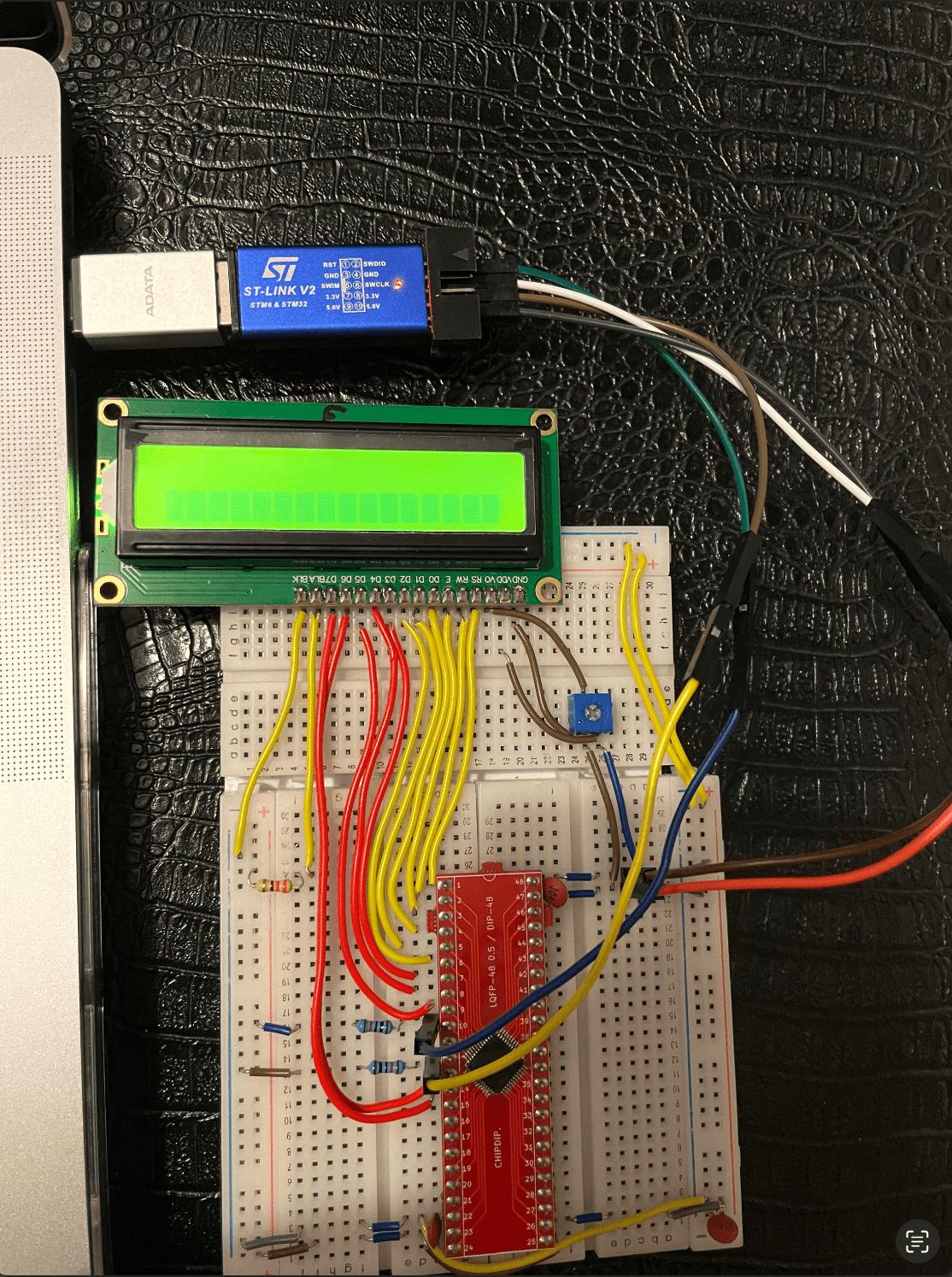
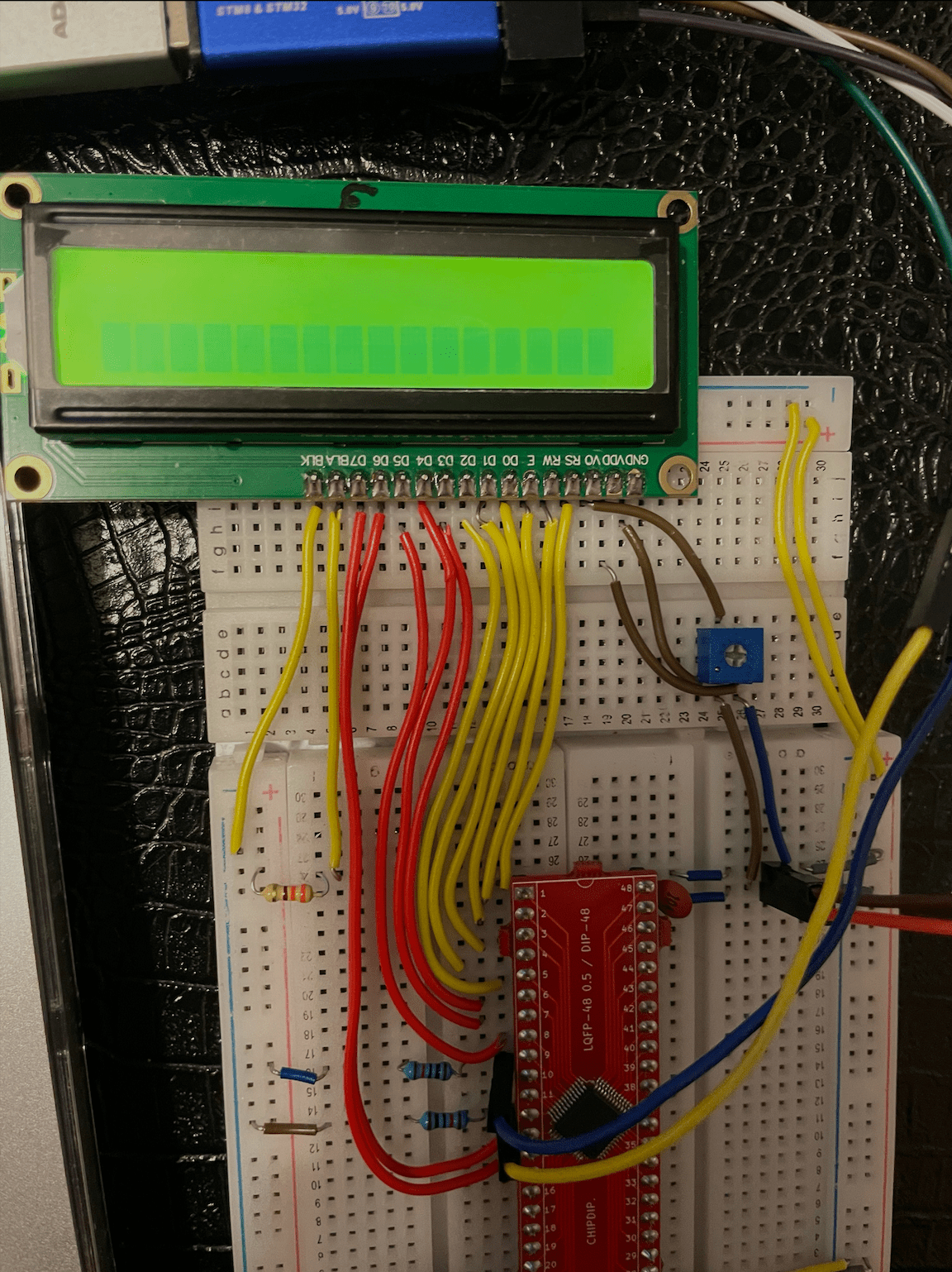
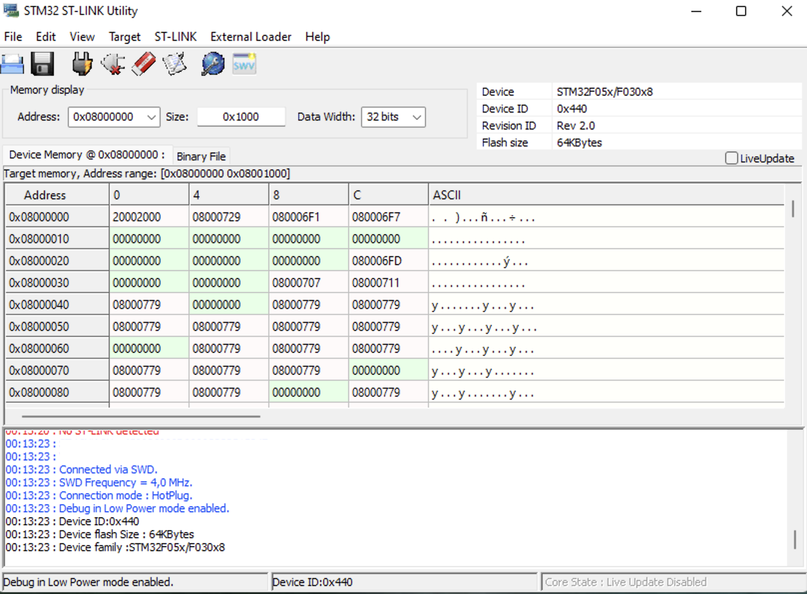
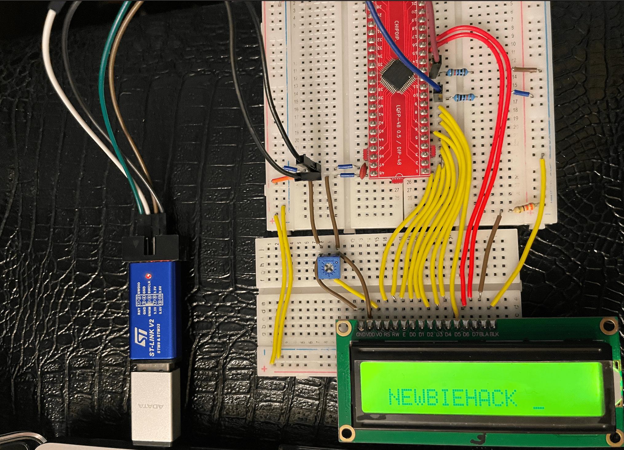
I'm learning mcu programming using ARM Microcontrollers: Programming and Circuit Building Volume 1 book by Patrick Hood-Daniel and I stuck on Chapter 17 "Add the LCD to the Circuit". I've connected to the target sucessfully, built and run the code to display "Hello World" but there's only one black boxes row on LCD. Other similar questions on the web are about Arduino only so I didn't find solution and I can't figure out the issue.

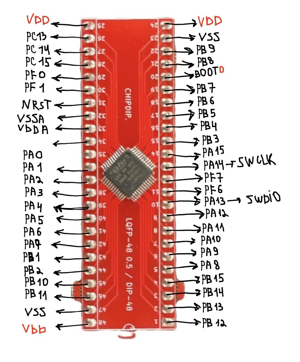
My board enter image description here enter image description here enter image description here

Here's my part of the code with pins and ports:

#define LCDD0Pin 15
#define LCDD0Port GPIOB
#define LCDD1Pin 8
#define LCDD1Port GPIOA
#define LCDD2Pin 9
#define LCDD2Port GPIOA
#define LCDD3Pin 10
#define LCDD3Port GPIOA
#define LCDD4Pin 11
#define LCDD4Port GPIOA
#define LCDD5Pin 12
#define LCDD5Port GPIOA
#define LCDD6Pin 15
#define LCDD6Port GPIOA
#define LCDD7Pin 3
#define LCDD7Port GPIOB
#define LCDEnablePin 14
#define LCDEnablePort GPIOB
#define LCDReadWritePin 13
#define LCDReadWritePort GPIOB
#define LCDRegisterSelectPin 12
#define LCDRegisterSelectPort GPIOB
#define TimeDelayBeforeEnable 4
#define TimeDelayBeforeDisable 8 
\$\endgroup\$
1
  • 3
    \$\begingroup\$ Only one row typically means you've not initialized the LCD correctly. Could be a timing issue or something else. Not all cloned controller chips HD44780-like are identical timing. \$\endgroup\$ Commented Dec 24, 2022 at 22:26

1 Answer 1

1
\$\begingroup\$

Thanks to @Sphero Pefhany from the comments section and to the author of the book Patrick Hood-Daniel who has directed me to focus on the delays. From Patrick's email advice:

Make sure your E pin is on/off at the correct time. Make sure that the E pin is on or off long enough. Make sure that the RS is in the correct mode for commands or characters. Make sure that you are in the read or write mode correctly. Do all of this very slowly so the LCD has time to process. In most cases, the LCD is busy and you need to wait for the LCD to become ready. Put an LED on the E, RS and the RW pins to make sure those are on/off at the correct time. Confirm with the LCD timing diagrams as I do in the book. If you are able to see the correct pin states, then the LCD will surely see them and not be busy.

I've set:

  • increment value i in the delay loop as volatile (if you'll set i to int compiler will just optimize it and delays will not work):

    void notExactTimeDelay(int timeDelay)  
    {   
      volatile int i;  
      for (i=0; i < timeDelay; i++)   
       {} 
     }
    
  • the time before Enable (E) is ON to 400000 #define TimeDelayBeforeEnable 400000, so notExactTimeDelay(TimeDelayBeforeEnable)

  • the time before Enable (E) is OFF to 800000 #define TimeDelayBeforeDisable 800000, so notExactTimeDelay(TimeDelayAfterEnable)

enter image description here

\$\endgroup\$
4
  • \$\begingroup\$ That's nice of the book author to provide quick support over the holiday period. \$\endgroup\$ Commented Jan 2, 2023 at 16:29
  • \$\begingroup\$ Yeah, I'm so thankful to him for the help! :) \$\endgroup\$
    – Diana
    Commented Jan 2, 2023 at 16:32
  • 1
    \$\begingroup\$ Note that there are much better ways of doing short delays than busy loops. Have a look at the chapter on timers! \$\endgroup\$
    – 2e0byo
    Commented Jan 2, 2023 at 17:43
  • \$\begingroup\$ Thank you! I’ll keep it in mind \$\endgroup\$
    – Diana
    Commented Jan 2, 2023 at 18:00

Your Answer

By clicking “Post Your Answer”, you agree to our terms of service and acknowledge you have read our privacy policy.

Not the answer you're looking for? Browse other questions tagged or ask your own question.