There's some potential for creativity here: the load can be used for battery balancing! Instead of switching the load to the batteries on a fixed frequency, attach the load to whichever battery has the higher voltage, with some hysteresis of course. This will provide charge balancing during both charging and discharging!
With the charger turned off, the batteries will be discharging, and their internal resistance will be rising as they do so. Eventually, the voltage on the unloaded cell will noticeably raise after the load is switched over to another cell. This will cause natural oscillation back-and-forth between the batteries. The switchover can be limited in frequency to make this acceptable.
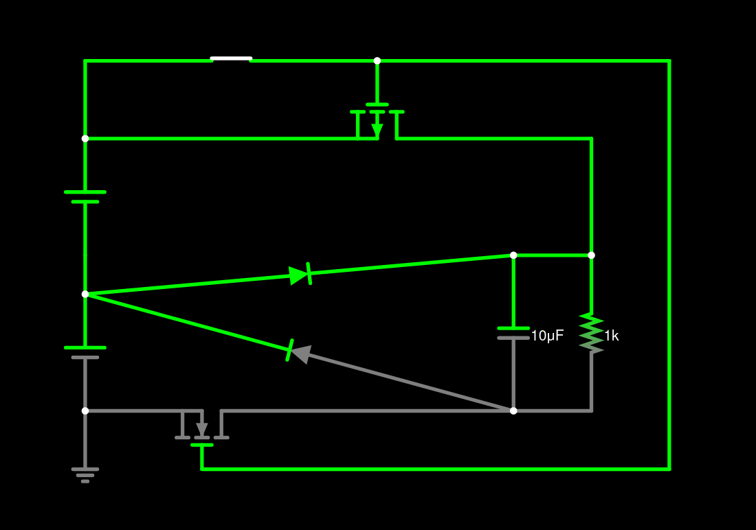
To minimize conduction losses, the diodes in the original schematic can be replaced with mosfets, so that they become ideal/synchronous rectifiers.
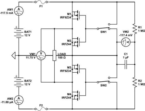
The overall idea would look something like the below. Vital fault protection devices are not shown for clarity (!).
SW1 and SW2 configure the load. Selecting either in the grounded position connects the respective battery to the load. If both switches are in the grounded position, the load is connected to both batteries in series. If both switches are in "not grounded" position, the load is disconnected. So that works out nicely: there is no invalid state. Of course connecting the load to 24V would not be desirable.

simulate this circuit – Schematic created using CircuitLab
In the model circuit above, the batteries each have internal resistance of 1Ω. This makes it easier to observe the differences between their voltages under load.
There should be a capacitor to "carry over" the load during switching. It doesn't need to be large, since the switchover happens in a fraction of a millisecond. Probably 1000uF/60V, 8000 hours, would be plenty.
The fuses F1, F2 should be slow-blow type.
Detecting which battery has a larger cell voltage is relatively easy: connect two precision resistors in series across 24V. Compare the center tap voltage, across filter capacitor C1, to ground: if it's positive, BAT1 has larger voltage, otherwise BAT2 has larger voltage.
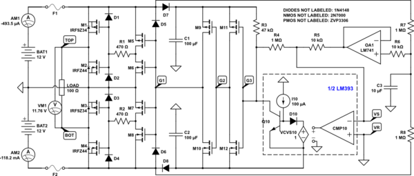
The circuit below is a rudimentary implementation of this idea.
M1-M4 switch the load. R1-R2 slow down transitions on M1-M4 somewhat, to reduce EMI. M5-M8 generate inherently non-overlapping drive for M1-M4. The sequence of switching always goes from one battery, to load disconnect, to the other battery. Both batteries are never connected at the same time, as this would make the load see 24V.
M9-M12 clean up the digital control signal - they act as two inverters in series.
R7-R8-C3 take a filtered measure of the imbalance between batteries, that is then buffered by the op-amp OA1.
The "1/2 LM393" block is a model of the internals of the LM393 comparator family. The comparator measures the polarity of the battery imbalance (upper vs lower).
24V*(R5/R4) is the hysteresis voltage. As it stands, the hysteresis is 240mV. Thus, the battery voltages have to differ at least 240mV in the opposite direction of the previous difference in order for the load switch to occur.
(R7||R8)*C3 establish the time constant for switching - about 5s.

simulate this circuit
Several things could be improved in the circuit, at the very lest:
Current drain via R3 - a different level translation network should be used to waste less power;
The relatively high supply voltage of the op-amp and comparator - they would run just fine from, say, +/-6V;
The relatively high current consumption of the op-amp and comparator - lower-current types would be preferable;
The protection of the "low current" part of the circuit from transients on the batteries/load.
The overall robustness of the gate driver circuitry. I've not evaluated it, but it may prove a bit of wishful thinking.
The response to a failure of a single fuse should be benign: the load will be in a stable state, either connected or disconnected, but without oscillation.
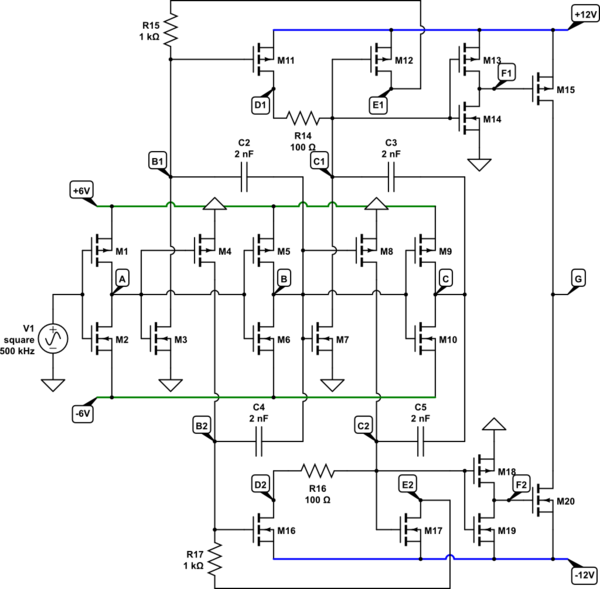
A better level translator that has no static current consumption is shown below.

simulate this circuit
The above can be discrete small-signal mosfets, or 4 x CD4007UB .
With the comparator and the op-amp running from +/-6V, the op-amp could be OPA170, the comparator TLV3701. The whole thing would run from a couple hundred microamps.


