1
\$\begingroup\$

While designing a Raspberry Pi CM4 application board, I found an issue with the power supply.

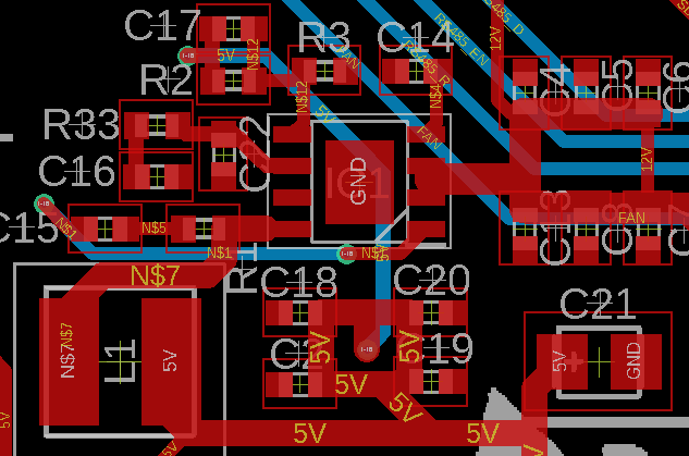
I selected the same IC as the official CM4 I/O board: the AP64501SP-13. I used even the same values for a 5 V regulator and tried to place the components on the board following a similar layout and respecting the IC recommendations: minimizing the distances between the components (input capacitors and input of the IC), solid ground, shortest traces, etc.

Schematic

Board layout

There are two issues. Maybe someone with experience with this IC (or in the field) could give me a hint:

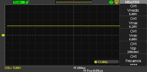
  1. Without load, the regulated output voltage does not match the expected 5 V, but instead it gives 6 V. This is not too much of a problem.

    Output when unloaded

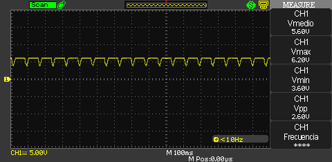
  2. With the CM4 connected, the output voltage starts producing an inadmissible ripple that messes up the CM4.

    Output when loaded

\$\endgroup\$
4
  • \$\begingroup\$ Please check your component values. The recommended values for typical application circuit(figure 1 in datasheet) is not similar for your values. Please check voltage feedback resistor and compansation line passives values. \$\endgroup\$
    – yardi
    Commented Jan 3, 2023 at 12:21
  • 4
    \$\begingroup\$ Is pin 7 unconnected? \$\endgroup\$ Commented Jan 3, 2023 at 13:22
  • \$\begingroup\$ (I don't "get' the layout&arrangement of components. The "recommended PCB layout" from the datasheet looks close to what I'd expect.) \$\endgroup\$
    – greybeard
    Commented Jan 3, 2023 at 16:04
  • \$\begingroup\$ @StainlessSteelRat, you are right. I added a jumping wire to GND but still nothing. \$\endgroup\$
    – Jon
    Commented Jan 25, 2023 at 19:19

1 Answer 1

2
\$\begingroup\$

The scope is at 100ms/div so it's a pretty slow ripple.

I don't see any vias under the chip to suck heat into the ground plane, so I'll bet on the chip overheating and tripping its thermal cutoff, then cooling down and starting up again.

The CM4 IO board gerbers and kicad files are available: it's a 4 layer board with three full ground copper layers under the chip to cool it.

\$\endgroup\$
1
  • \$\begingroup\$ Thanks for the tip, I will be sending to prototype another board with your suggestion and @StainlessSteelRat and will post back soon with the results. \$\endgroup\$
    – Jon
    Commented Jan 25, 2023 at 19:18

Your Answer

By clicking “Post Your Answer”, you agree to our terms of service and acknowledge you have read our privacy policy.

Not the answer you're looking for? Browse other questions tagged or ask your own question.