5
\$\begingroup\$

Here are some preliminary information before asking the question:

When piezoelectric force sensors are subjected to a stress, they produce a charge that is proportional to the force. The amount of charge generated by such a sensor is given as:

Q = F × d where F is the force and d is the piezoelectric coefficient.

Although the name charge amplifier suggests that somehow electric charge is being amplified. The truth is that this type of amplifier just converts electric charge into a proportional electric voltage

Charge-emitting transducers produce an output charge, ∆Q, and their output capacitance remains constant. This charge would normally produce an open-circuit output voltage at the transducer output equal to ∆Q/C.

Piezoelectric signals cannot be read using low-impedance devices. The two primary reasons for this are (1) high output impedance in the sensor results in small output signal levels and large loading errors and (2) the charge can quickly leak out through the load. In order to overcome these problems to a great extent, a charge amplifier is commonly used as the signal-conditioning device for piezoelectric sensors. Because of impedance transformation, the impedance at the output of the charge amplifier becomes much smaller than the output impedance of the piezoelectric sensor. This virtually eliminates loading error and provides a low-impedance output for purposes such as signal communication, acquisition, recording, processing, and control. Also, by using a charge amplifier circuit with a relatively large time constant, the speed of charge leakage can be decreased.

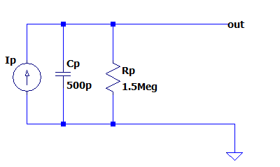
So what I understand from above if we don't use a charge amplifier and directly couple the piezo force sensor to a scope or an ADC with lets say 100Meg input impedance, we still get the force profile(?) Such sensor's model is give as below or here:

enter image description here

We can then write the following:

i_p = Cp*dVout/dt + i_Rp
Q_p = Cp*Vout + Q_Rp
Vout = (Q_p - Q_Rp)/Cp

Since Cp is constant, even though we don't use an amplifier, it seems to me the Vout is still proportional to the Q_p which is proportional to force. I can see there's some loading effect here only.

And if a charge amplifier is uses as below:

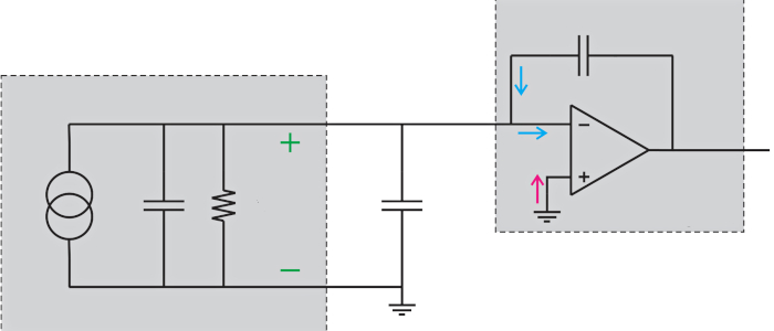
enter image description here

And if you look at the analysis of this circuit here, the feedback capacitor Cf accumulates all the charge and can provide gain. In this case. it seems to me that the loading effect is eliminated and the low voltage signal of the high impedance sensor is amplified.

Here are my questions:

But is that the only benefit of such charge amplifier? Because if one can manufacture a piezo force sensor which can output enough voltage and directly cupules it to an ADC wouldn't he get a linear relationship between the Voltage he reads and the force?

The time constant from the feedback capacitor and resistor Cf and Rf can change the response time of the sensor. I'm wondering is this the core reason to use a charge amplifier. Because if we don't use a charge amplifier the Vout still is linear with the force if I'm not wrong. So is charge amplifier still needed even though such a sensor outputs enough voltage?

\$\endgroup\$
5
  • 2
    \$\begingroup\$ Piezoelectric signals cannot be read using low-impedance devices <-- that is incorrect. A charge amplifier is the ultimate low input impedance amplifier. It's input impedance is nominally zero ohms. \$\endgroup\$
    – Andy aka
    Commented Jan 6, 2023 at 10:40
  • \$\begingroup\$ Maybe your question should focus on why charge amplifier are used in preference to high-impedance amplifiers (rather than asserting things about them that are inaccurate)? \$\endgroup\$
    – Andy aka
    Commented Jan 6, 2023 at 10:55
  • \$\begingroup\$ @Andyaka Im planning to add some examples about where my confusion arises. I will add some SPICE results. For instance I can get same output with a buffer and an amplifier instead of a charge amplifier or without any amplifier. But I can only set the time constant in charge amplifier. (If Im not wrong) \$\endgroup\$
    – floppy380
    Commented Jan 6, 2023 at 10:59
  • \$\begingroup\$ @Andyaka " why charge amplifier are used in preference to high-impedance amplifiers " I think you articulated better than me. \$\endgroup\$
    – floppy380
    Commented Jan 6, 2023 at 11:07
  • 1
    \$\begingroup\$ I've rolled back the recently changed question because it distorts a question quote given in my answer and now favours the answer recently given by the person editing the question. It's a slippery slope when this is done. \$\endgroup\$
    – Andy aka
    Commented Jan 6, 2023 at 18:30

4 Answers 4

2
\$\begingroup\$

Is that the only benefit of such charge amplifier?

You might be missing the main point of a charge amplifier.

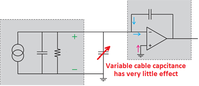
A charge amplifier produces a virtual ground at its input. This means that all the charge has to flow into the feedback capacitor (standard op-amp action) and, none of the charge flows into the (usually significant) capacitance of the cable that connects the sensor to the virtual ground input. Within reason, you can make the cable any length you want and, all the charge still flows into the feedback capacitor.

Thus, a charge amplifier permits (within reason) any length of cable between sensor and amplifier without degrading the signal quantity. This is why charge amplifiers are used.

Piezoelectric signals cannot be read using low-impedance devices.

That is incorrect; a charge amplifier has theoretically (and ideally) zero Ω input impedance.

enter image description here

I'm wondering is this the core reason to use a charge amplifier

The core reason is to counteract cable capacitance between sensor and sensing circuit. If the distance the signal travels is very small then, you can use a high-impedance voltage amplifier.

\$\endgroup\$
15
  • 1
    \$\begingroup\$ "This means that all the charge has to flow into the feedback capacitor" My point was if we dont use charge amplifier and if we translate more than half of the charge "not all charge" what are we missing here? Arent we still obtaining the force profile by directly coupling to a high impedance ADC? (There will charge loss but we still have linear relation between the force and Vout)(?) \$\endgroup\$
    – floppy380
    Commented Jan 6, 2023 at 11:26
  • 1
    \$\begingroup\$ You will obtain a signal but that signal will be affected by cable capacitance. However, linearity will be maintained but, because of the unknown cable capacitance, the "calibration" is also unknown and this means you cannot relate force to voltage accurately or with certainty @floppy380 \$\endgroup\$
    – Andy aka
    Commented Jan 6, 2023 at 11:48
  • \$\begingroup\$ Thanks great comment! I So calibrating would solve the issue then if we are fine with the output voltage of the sensor(direct coupling to ADC) there's no need for a charge amplifier. But the charge amplifier also can set the time constant by Cf Rf for a good response. Do you have a comment on that? Direct coupling will suffer from that? (Piezo sensor does not maintain current long time) \$\endgroup\$
    – floppy380
    Commented Jan 6, 2023 at 12:39
  • \$\begingroup\$ What Cf and what Rf do you speak of? \$\endgroup\$
    – Andy aka
    Commented Jan 6, 2023 at 12:41
  • 1
    \$\begingroup\$ I have actually answered that question; "I'm wondering is this the core reason to use a charge amplifier" in my answer (the core reason being variations in cable length). Rf is not anything to do with response time (except at frequencies below the limit you are interested in). \$\endgroup\$
    – Andy aka
    Commented Jan 6, 2023 at 13:09
4
\$\begingroup\$

Building a conceptual circuit

I will reveal the idea behind this clever circuit solution in five consecutive steps. Each step is illustrated by a picture consisting of two parts - a hydraulic analogy is shown on the left and its corresponding electrical circuit on the right.

1. Input quantity. The charge amplifier is designed to amplify signals from piezoelectric sensors. They are fully capacitive and have the behavior of a charged capacitor C1 with charge Q1 and voltage VC1 (Fig. 1b) whose hydraulic analogy is a vessel full of water with volume VH1 and height H1 (Fig. 1a).
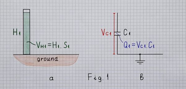
Charged capacitor

Fig. 1. Hydraulic analogy of а full vessel (a); charged capacitor (b)

So, the voltage across the capacitor (sensor) can serve as an input quantity... and we can think of the piezoelectric sensor of as a voltage source. It cannot be directly applied to a low-resistive load since it will be quickly discharged; it is usually buffered by some kind of a voltage follower.

2. Problems. Only, the stray capacitances between the cables and ground shunt the sensor; they are also charged and an error is introduced. They are charged because there is a voltage; they will be not charged if the input voltage across the capacitor would be zero... but we need it... so it cannot be zero. How do we solve this contradiction?

Maybe the hydraulic analogy can help as? What do they do in industry when it is impossible to measure directly the liquid level in a tank? They use "communicating vessels" - Fig. 2a.
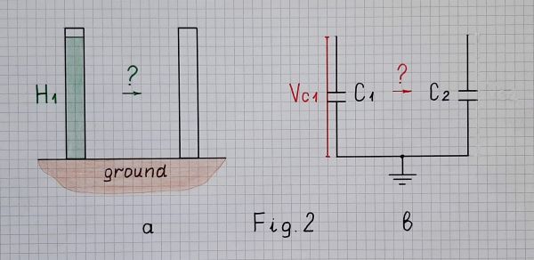
Measuring by copying?

Fig. 2. How do we measure the level of water (a)... and the voltage of the capacitor (b)?

3. Trying to solve the problem. So, the powerful idea is to copy the voltage of the first capacitor C1 to another capacitor C2 and then to measure the voltage VC2 across the second capacitor. And since we want the voltage across the first capacitor to be zero, we should move the charge from the first capacitor to the second one. Let's do it - connect C1 to C2 (Fig. 3b); in the hydraulic analogy, connect the two vessels by a pipe - Fig. 3a.
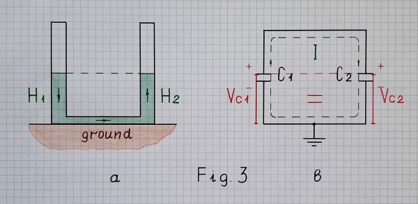
Measuring by copying

Fig. 3. Measuring the level of water (a) and the voltage of the first capacitor (b) by copying at the end of charge redistribution

To transfer all the charge, current must flow the whole time. In order for current to flow, there must be a difference between the two voltages. So the voltage of the initially charged capacitor C1 must always be higher than the voltage of the charging capacitor C2.

But when connecting the charged capacitor C1 to the empty C2, only half of the charge moves from C1 to C2 (suppose C1 = C2) and the voltage reduces double; after that the current stops flowing (see Two capacitor paradox). What should we do to make the rest of the charge in C1 go to C2?

4. The clever idea. In the hydraulic analogy, we must make sure that the water level in the right vessel is always lower than that of the left. And here we just have to guess that the vessels may be movable (if we connect them with a flexible hose). There are two options - to raise the left vessel or to lower the right vessel. Let's choose the second one because it will lead us to the desired circuit. So, we can start lowering the right vessel so that the water level in it is always zero (Fig. 4a)... like a kind of a "bottomless vessel".
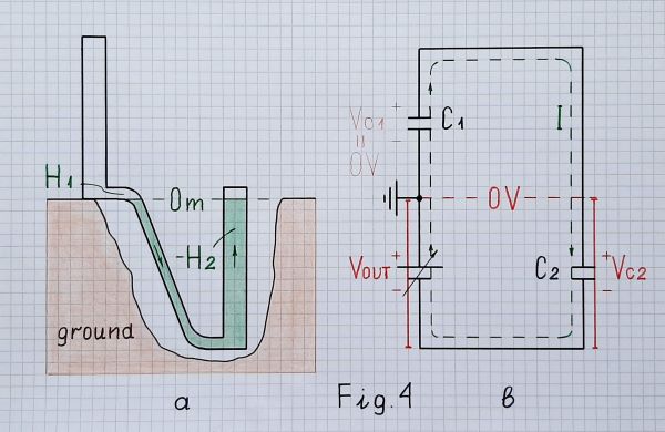
Compensating the quantity

Fig. 4. Compensating the level of water (a) and the voltage of the second capacitor (b) at the end of charge redistribution

Similarly, in the electrical circuit (Fig. 4b), we can begin "moving down" VC2 by the help of a following negative voltage source VOUT. It copies the voltage across C2 and adds this voltage (VC2) to VC1 in a series manner (according to KVL when travelling the loop). Note I have drawn the two voltage sources (VC1 and VOUT) one below the other to show that they are connected in series and in one direction so that their voltages are added (like a battery of two cells).

As a result of applying this clever trick, VC2 is neutralized; the combination of C2 and VOUT behaves as a "virtual piece of wire" with zero voltage... and C1 is "virtually shorted". As a result, all the charge will move to C2. There is no charge in C1... there is no voltage across it...

The same trick is used in all kinds of op-amp inverting circuits with negative feedback where the op-amp output voltage compensates the voltage drop across the second element (R2, C, L, D, etc.) by adding the same voltage in series. It is further developed in circuits with S-shaped true negative resistance (VNIC converters) by adding a multiplied voltage. This is the great Miller's idea.

5. Implementation. So, this idea can be implemented by a simple electrical arrangement of three elements in a loop - C1, C2 and VOUT (Fig. 5a). In this conceptual electrical circuit, VOUT is a variable voltage source that follows VC2. In contrast to the "geometrically drawn" pictures above, here I have not drawn a reference point (ground) to show that it is not absolutely necessary for the conceptual circuit.
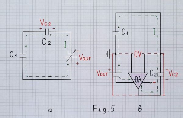
Electrical implementation

Fig. 5. Conceptual electrical circuit diagram (a) and electronic circuit of a charge amplifier (b) at the end of charge redistribution (draft)

Drawn in such a neat way, Fig. 5a can give us the simplest explanation of the circuit:

We have two capacitors in series - the one is full (charged) to a voltage V and the other is empty (discharged)... and we want to move the charge from the full capacitor to the empty one. For this purpose, we connect another voltage source with the same voltage V in series and in the same direction. The two voltages are added and the same current I begins flowing through both capacitors. As a result, the full capacitor begins discharging and the empty capacitor charging (the charge exits the first and enters the second capacitor). Finally, the first capacitor is fully discharged (empty) and the second capacitor is fully charged (full) to the input voltage V. The current stops flowing... and all the charge of the first capacitor is transferred to the second capacitor.

Briefly, to "drive away" the charge from C1 to C2, connect a source with voltage VC1 in series and in the same direction.

Indeed, our case is a little more sophisticated - the additional voltage is not constant but gradually increasing. It follows the voltage across the second capacitor and, at the end of the process, it is maximum.

Note that if the second capacitor has smaller capacitance, it will charge to a higher voltage... and we will get an amplifier (the hydraulic analogy can also explain this trick). The gain of this "electrical charge ampifier" will be C1/C2.

Now it remains only to replace VOUT with an op-amp so that to make it follow VC2... and we obtain the electronic circuit of an "ideal" charge amplifier - Fig. 5b.

So, what does it amplify?

From all these considerations, we can conclude that the charge amplifier, like any amplifier, ultimately amplifies voltage... the voltage across the input capacitor which is proportional to the charge inside it. Only, for some reasons considered above, it amplifies not the very input voltage but a copy of this voltage created across another capacitor by transferring the charge. More precisely speaking, the "amplification" is obtained by changing the ratio C1/C2... and the op-amp only follows the voltage across C2.

In this DC application, the input source is simply a charged capacitor that can be considered as a kind of "exhausting voltage source"(see Fig. 6 below as an example). Only in AC applications (e.g., the vibrometer shown in Fig. 7), it can be thought of as an "exhausting current source" (a voltage source with significant capacitive internal impedance). That is why, in this case, a piezoelectric sensor can be emulated by a sine wave signal generator with a capacitor in series to its output.

And yet, where does the input current flow?

It is interesting that stray capacitances provide a path for the input current to ground... but for some reason the current does not go through there. Let's see why…

When the input current "arrives" at the summing point (op-amp inverting input), it must "decide" where to proceed - through the parasitic capacitance to ground or through C2 to the op-amp output. After a short hesitation:-) the current "gives up" the first path because there is no voltage difference and chooses the second path because there the voltage is "under" the ground. So, the rule is that current flows to the point of lower voltage and not at all to the point of the same voltage.

Real charge amplifier

Resistor in parallel. In real op-amp circuits, we have to provide paths for the op-amp input bias currents. In this fully capacitive circuit there is no path for the bias current of the inverting input. The usual solution is to connect a resistor with very high resistance (typically 1 G) in parallel to C2. Thus, in regard to DC, the circuit is a follower with zero input voltage (of the ground).

So the circuit diagram of a real charge amplifier is more complex. Here is an AD example where the charge amplifier is driven by a piezoelectric shock sensor accelerometer:
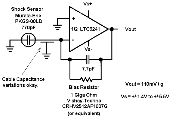
AD charge amplifier

Fig. 6. A real charge amplifier

Resistor in series. To connect two voltage sources (charged capacitors) in parallel is a bad idea since a conflict appears and the current should be infinite... but exactly this arrangement is here. The usual solution to "soften" the conflict is to connect a resistor with a relatively low resistance in series to the input. The same problem appears in the op-amp differentiator; usually, they explain it by an enormously increased gain. Such a more sophisticated version was used in Brüel & Kjær’s vibrometers in the 80s:
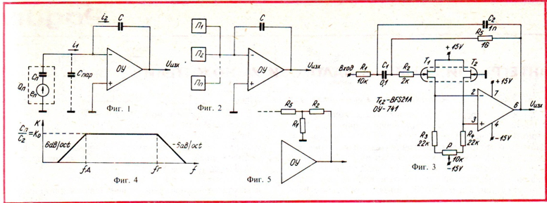
Charge amplifier (Brüel & Kjær)

Fig. 7. A more sophisticated real charge amplifier (‘Radio and TV’ BG magazine, August, 1983)

Conclusion

By applying a few basic didactic principles, the basic idea behind this fully capacitive circuit is revealed: measuring indirectly the voltage across a charged input capacitor (sensor) by moving (redistributing) the charge to another capacitor. For this purpose, the input capacitor is discharged through the output capacitor whose voltage is compensated by an equivalent voltage in series... and the compensating voltage is used as an output voltage.

The benefits of this solution are that input stray capacitances are shorted, the output voltage is buffered and it can be amplified by simply changing the ratio C1/C2.

\$\endgroup\$
3
  • 1
    \$\begingroup\$ I think this answer is very pedagogical and shows a clear argument why we need a capacitor in the amplifier rather than another element. However, I'm not sure I'd say " the input current (...) chooses the second path..." because it clouds the fact that the current is, actually, produced by the amplifier in an effort to keep its error signal as close as possible to 0 (i.e. the current generated by the op-amp has the opposite sign). Even though, mathematically, both of our statements are equivalent, conceptually they are different. \$\endgroup\$
    – Designalog
    Commented Jan 7, 2023 at 7:51
  • \$\begingroup\$ @ErnestoG, Thanks... interesting thoughts... We can imagine it like this: At the first moment, part of the input current tries to pass through the stray capacitance but the op-amp starts to lower its output voltage and absorbs it through the larger feedback capacitor. The two capacitances form a current divider which is ordinary at first but then, when the op-amp artificially increases the feedback capacitance, it becomes virtual. \$\endgroup\$ Commented Jan 7, 2023 at 8:13
  • 1
    \$\begingroup\$ sounds like you're saying the same thing. But ok, each one to his own. \$\endgroup\$
    – Designalog
    Commented Jan 10, 2023 at 11:37
1
\$\begingroup\$

The charge of the piezo is unambiguously related to the current as follows:

$$ I_{source} = \frac{dq_s}{dt} $$

However, if we try representing the signal as a voltage, we'll find that it'll depend on the capacitance of the piezo, which is a never a fixed number.

$$ V_{source} = \frac{q_s}{C_s} $$

Therefore, for an accurate transfer of the charge signal, it's preferable to assume the piezo as a current source. Thus, we need to interface with a very low impedance so that its source impedance doesn't interfere. The charge amplifier provides such interface.

An ADC has a high input impedance (AFAIK, not an ADC expert), therefore, we are already disturbing the signal source in this way as we'll be trying to sense its voltage and not the current.

Another problem is that, such a source input impedance, will disturb the acquisition time of your ADC massively as you must add your source impedance to the ADC input impedance to compute the new time constant.

A charge amplifier also helps with that, since it provides a current-to-voltage transfer. Thus, it has low output impedance due to the shunt feedback at the output. That means, the acquisition time of your ADC increases negligibly.

Now, you might say, but what if the ADC input impedance is ~2x orders of magnitude higher than that of the piezo? Well, in theory that might be possible, but I think then, the sampling capacitors would have to become very small until the point that it isn't practical to manufacture them.

\$\endgroup\$
5
  • 1
    \$\begingroup\$ If we dont use amplifier and direct couple the sensor to very high impedance ADC and apply a known force to the pizeo sensor and measure the output voltage at different points of force. Wouldnt we obtain a accurate Force Voltage relation/function? (I don’t need to know charge. And in my case imagining the cable length is always fixed same as in calibrated way.) In that case what can go wrong with direct coupling if we want force as a function of output voltage? \$\endgroup\$
    – floppy380
    Commented Jan 6, 2023 at 17:34
  • \$\begingroup\$ Deformations in the piezo normally translate into variations of the source capacitance. Therefore, I doubt that you'll have s linear relation voltage to force. Second, you have to consider the maximum source impedance your ADC can handle. This is because the sampling capacitors will charge much slower the higher your input impedance is. If they take too long to charge, you'll have erroneous readings in your ADC as the sampling will happen half-way the charging of the capacitor. \$\endgroup\$
    – Designalog
    Commented Jan 6, 2023 at 19:43
  • \$\begingroup\$ @floppy380 I'm curious as to why you want to skip the charge amplifier so much? I mean, you can try whatever you want, but I am fairly certain your ADC readings won't be a monotonous linear curve. You can calibrate anything you want, but I doubt a one-time calibration will be reliable in the long run. \$\endgroup\$
    – Designalog
    Commented Jan 6, 2023 at 19:47
  • \$\begingroup\$ Eight needed to be read simultaneously so eight amplifier needed as signal conditioner. Makes space issues not acceptable. Also what do you think about “time constant” of the charge amplifier circuit . Should it be set in a way according to input force frequency? \$\endgroup\$
    – floppy380
    Commented Jan 7, 2023 at 12:27
  • \$\begingroup\$ @floppy380 2 quad op-amps and 8 pairs of 0402 RCs cause too much space issues? Your company is willing to not allocate space to potentially sacrifice a linear force-current transfer? Anyway, the time constant just need to be lower than your minimum frequency of interest of your current signal. I'd be very curious to see how your system would work without signal conditioning. I don't think it would but who knows... \$\endgroup\$
    – Designalog
    Commented Jan 8, 2023 at 21:13
0
\$\begingroup\$

But is that the only benefit of such charge amplifier? Because if one can manufacture a piezo force sensor which can output enough voltage and directly couples it to an ADC wouldn't he get a linear relationship between the Voltage he reads and the force?

A piezo transducer converts the physical quantity into charge, not voltage. You need something to then convert charge to voltage. This happens by default if there is some distributed and/or parasitic capacitance present in the circuit. But these capacitances are variable, temperature- and vibration-sensitive, and may have lots of dielectric absorption and other nonlinearities.

In circuits, most generally, the voltage and current are independently controllable. So, if we hold the voltage across the parasitic capacitances constant, the charge signal will become current signal, with no voltage change.

This is what the charge amplifier does. It is a short that measures the charge (time integral of current) that it has shorted to virtual ground.

\$\endgroup\$

Your Answer

By clicking “Post Your Answer”, you agree to our terms of service and acknowledge you have read our privacy policy.

Not the answer you're looking for? Browse other questions tagged or ask your own question.