0
\$\begingroup\$

I am experimenting with digital counters and for one application it would be useful to generate a set of four pairs of 3-bit values used for comparing (Cx) and resetting (Rx) a counter. Since there are four possible outputs I think that it's possible to use two SPDT switches (Sx) that can be connected to GND and VCC to create these values.

Proposed truth table:

enter image description here

Calculating Cx and Rx values can be easily done with standard logic gates as follows:

C2= (¬S1) and (¬S0) = S1 nor S0;

C1= S1 xor S0;

C0 = S0;

R2 = 0;

R1 = ¬S1;

R0 = ¬S0;

In terms of used components (4000-series ICs) this would require a Hex Inverter (CD4049), a XOR Gate (CD4070) and either a NOR gate (CD4001) or an AND Gate (CD4081). Total of 3 ICs.

I was wondering if there is a more elegant solution for such a simple task. Perhaps problematic C2 and C1 value can be generated using discrete components. I would appreciate any improvement suggestions.

\$\endgroup\$
2
  • 1
    \$\begingroup\$ Logic gates sound elegant but, if you think discreet components are elegant then that's up to you. Some people may think using an MCU is elegant. Others might think using tubes are more elegant. In other words, it boils down to what a person thinks is "elegant". \$\endgroup\$
    – Andy aka
    Commented Jan 13, 2023 at 13:28
  • 1
    \$\begingroup\$ You can invert something by XORing it with 1 or NORing it with 0 or itself. \$\endgroup\$ Commented Jan 13, 2023 at 14:11

2 Answers 2

1
\$\begingroup\$

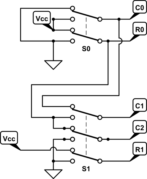
use instead multipole switches:

schematic

simulate this circuit – Schematic created using CircuitLab

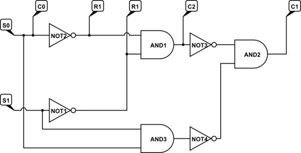
Or use and gates and iverters.

schematic

simulate this circuit

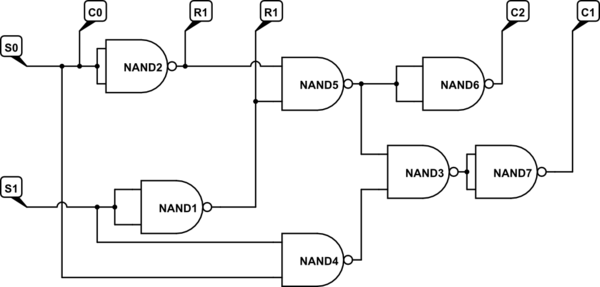
or use all nand gates.

schematic

simulate this circuit

\$\endgroup\$
1
\$\begingroup\$

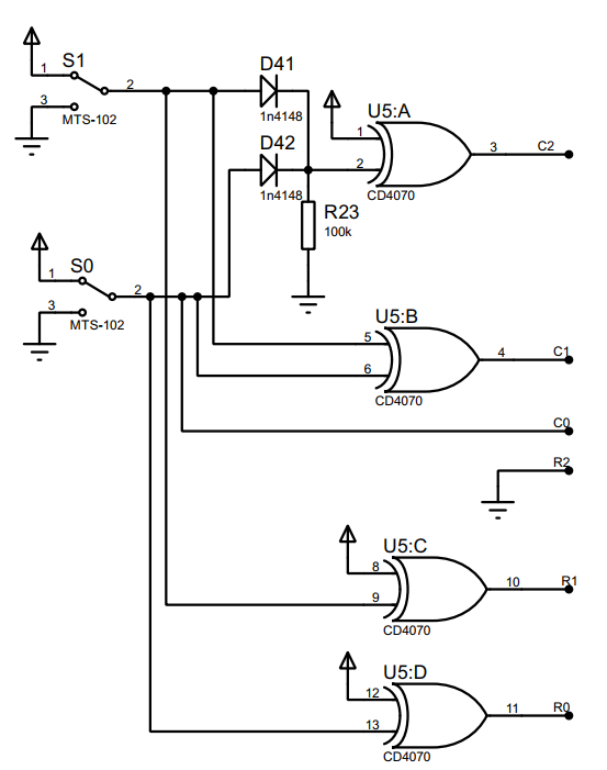
Come to think of it, it seems that this can be accomplished using only one XOR gate IC and couple of passives:

C2= (¬S1) and (¬S0) = S1 nor S0 = (S1 or S0) xor 1; \ XOR used as an inverter

C1= S1 xor S0;

C0 = S0;

R2 = 0;

R1 = ¬S1 = S1 xor 1; \ XOR used as an inverter

R0 = ¬S0 = S0 xor 1; \ XOR used as an inverter

OR gate needed for C2 can be accomplished with two diodes and pull down resistor.

So my proposed schematic is as follows: enter image description here

\$\endgroup\$

Your Answer

By clicking “Post Your Answer”, you agree to our terms of service and acknowledge you have read our privacy policy.

Not the answer you're looking for? Browse other questions tagged or ask your own question.