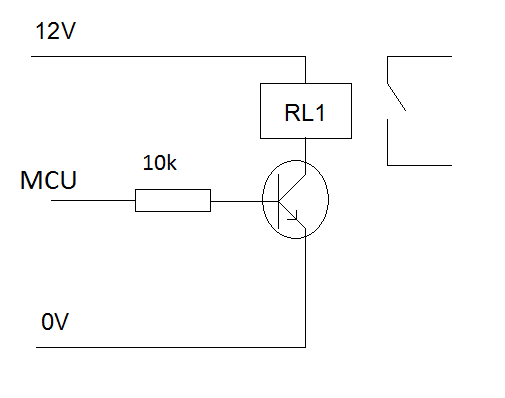
I want to control a freezer using a microcontroller and relay, and be able to set a higher higher temperature for dry curing meats. I realize there are off-the-shelf solutions but I kind of want to build it from scratch. I'm familiar enough with microcontrollers and small signal relays, but I've never tried to switch mains voltages or inductive loads. If the freezer draws 2A (AC steady state, at 110v, not sure what starting current is) what relay would you recommend, and how would you recommend I drive it? I'm thinking of using a 15-25A DPST relay for the load w/ 12V coil voltage. DPST because I'd switch both hot and neutral. And a 12V relay (with V_coil matching my uC supply voltage) in front of the power relay to drive the power relay.
Here's a selection digikey relays matching the power relay criteria I've mentioned... http://www.digikey.com/scripts/dksearch/dksus.dll?FV=fff40010%2Cfff80367%2C16040015%2C16040017%2C16040018%2C16040019%2C1604001a%2C16080007%2C16080008%2C1608000a%2C16080039&k=relay&vendor=0&mnonly=0&newproducts=0&ptm=0&fid=0&quantity=0&PV72=13&PV72=35&PV72=2
BTW, I'm comfortable wiring mains voltage. I don't mess around with it unless the circuit is OFF! I've just never interfaced my electronics stuff to my house wiring.
One point about DC power source: I'll probably use a silver box from an old PC to provide the uC voltage and 12V relay supplies. This will be on the same circuit as the power relay for the freezer.
I can provide more clarification if needed. Thanks.
Edit: One person I spoke to had suggested switching both line and neutral, and I'd read it on a forum somewhere as well (can't remember where). I plan to keep the GND connection hard tied to a common ground throughout the system / house.

