Background
In the process of trying to fix an LNA input impedance match, we discovered we need to understand more about Smith charts! The question is the at the bottom of this post, here's some background:
We are trying to fix the input match on an LNA. As the input match is currently designed it gets an VSWR of 1.7 . This is pretty good but we thought, maybe, ignoring parasitics, we can make it better as follows:
- Measure S11 using a VNA (.s1p) and optimize an arbitrary ideal network that provides a good match. We call this ideal network "Z_Match":
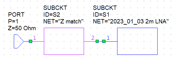
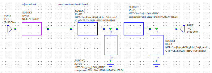
- We then place "Z_Match" in series with the component models (.s2p) of the existing matching circuit that was measured with the VNA. The ignoring parasitics, theoretically the RF behavior of this combined network is what we need to get a better match. We call this the "adjusted old match":
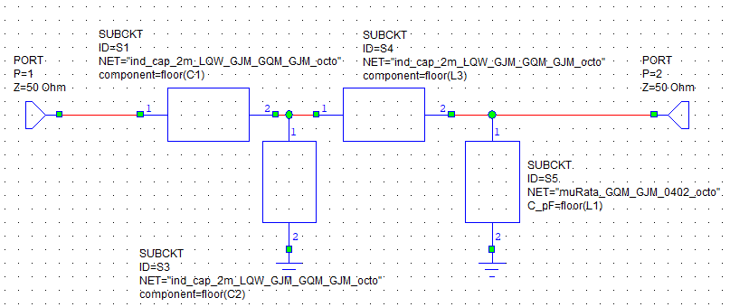
- We can then use the "adjusted old match" to optimize a "new match" with component models that has the same behavior as the "adjusted old match". As you can see the "new match" has the same footprint as the old match but with different components so we can swap them out and hope for a better match (C1, C2, L3, L1 are optimized indexes into MDF data files):
Thus, when
$$ {S11}_{adjustedoldmatch}-{S11}_{newmatch} \approx 0 $$
then the "New Match" network is nearly as good as it would be if the old network where augmented with the ideal matching network.
Results
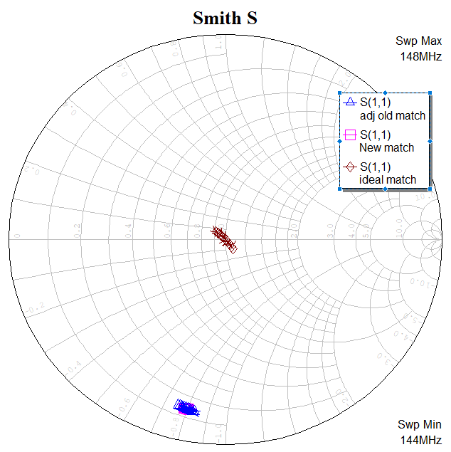
So we went to work and ended up with a great optimization. Here's the Smith chart plotting S11:
As you can see above, the "new match" and the "adjusted old match" are right on top of each other, and the ideal match is right in the middle where we want it.
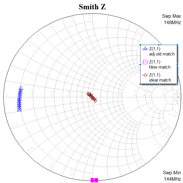
Out of curiosity, I wondered what the smith chart of Z11 looked like, and was surprised to see that the Z11 behavior does not overlap, in fact it appears to be exactly 90 degrees apart:
Questions:
Why does the Z-parameter Smith chart show "new match" and "adj old match" at 90 degrees apart when the S-parameter Smith chart is nicely overlapped? What is the difference between a smith sharp plotting S11 compared to a smith chart plotting Z11?
If not S11, then which parameters should I optimize to be equal between the "adjusted old match" and "new match"?
Does S21 matter In this case since we are only trying to optimize the input and not concerned about phase shift through the network?
More info:
- This is an educational project.
- Here is a short video with more information about our LNA board and expected match: LNA Circuit Board Arrived!
- The LNA component is the Qorvo QPL9547.
- Optimization used Cadence's (awesome!) AWR Microwave Office software.
- Frequency is ~144 MHz (wavelength ~2m)

