4
\$\begingroup\$

For the past few weeks I have been working with the new revision of my ARM Cortex M4 design that I posted about a month ago, thanks again to everyone who provided me with much needed guidance and information! Anyways I am still having trouble getting my ARM to program via JTAG programmer. I am using the NXP LPC4337JBD144 ARM Cortex M4, I am using their LPCXpresso IDE and LPC-Link JTAG/Debug module. So far after many attempts I have been unable to get the JTAG interface to recognize my chip as a programmable target.

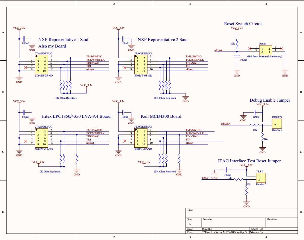
When creating this new design (the first did not work) I was very careful to check the datasheet and with NXP representatives to make sure that the hardware configuration was absolutely correct before having the board fabricated. My original design suffered from an improperly wired JTAG connector, lack of bypass caps on all voltage inputs, and the lack of jumper pins on crucial JTAG configuration pins. When setting up the JTAG connector circuit I consulted NXP support and the datasheet for the chip. The datasheet instructed me to only have pullups on two of the pins, one NXP rep told me to pull all pins down with 10k ohm resistors, and another told me to pull all pins high with 10k ohm resistors. Around that time I posted here and consulted with friends far more experienced than me, between those sources I decided to pull all pins high with 10k pullups.

Over the weekend I swapped out the chip maybe thinking that I might have damaged the first one but I was still unable to get it to program, so I went through all the datasheet but I could not find a solution when reading through the section on the JTAG interface. My next thought was to look at the evaluation boards made for the same ARM that I am using. I discovered that the boards from Hitex and Keil had unique JTAG connector wiring, both different from what NXP instructed me to do. This discovery has been rather confusing and what I really would like to know is which is the right way to wire it? Is there a standardized wiring scheme meant for all Cortex M ARM based micro?

Here is a schematic document I made illustrating the different configurations as well as the reset circuit and TRST/DBGEN jumper pins. https://www.dropbox.com/s/ohpuhu3wsq9yfhj/ARM%20Cortex%20M%20JTAG%20Wiring.pdf
\$\endgroup\$
0

3 Answers 3

5
\$\begingroup\$

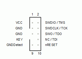
This is the official ARM Cortex JTAG/SWD connector diagram:

Cortex 10 pin connector

You should follow the data sheet/user manual about any resistors that are required. SWD pins on other LPC chips are usually pulled up internally.

The LPCXpresso IDE might be defaulting to the SWD interface. You need to select the JTAG interface, which is probably what the LPC4337 uses initially.

\$\endgroup\$
2
  • 1
    \$\begingroup\$ This doesn't really seem like an answer to the question, since the question itself is already far more researched and detailed than what this answer offers. The SWD observation could make a good comment though. \$\endgroup\$ Commented Apr 10, 2013 at 15:15
  • \$\begingroup\$ I populated a new PCB (I received 3 when I ordered) with the pullup configuration found in the datasheet and I still have nothing. I think I might have another idea as to why my board is not programming, the VBAT pin is left unconnected and floating, could that be the cause of the chip not being recognized by the JTAG programmer? \$\endgroup\$ Commented Apr 12, 2013 at 5:25
4
\$\begingroup\$

first off thanks for looking at my long post and offering advice! Just now I found the root of my problem, the reset button was wired incorrectly holding the LPC4337 permanently into reset mode, this made it impossible for the chip to startup, I have since removed the reset switch and got the board running. It actually draws the right amount of current and it is recognized by the JTAG programmer, I am using the pullup resistor configuration found int he data sheet which is a 10k pullup on the TDO pin and one on the TCK pin.

Thanks for all your help everyone!

\$\endgroup\$
3
\$\begingroup\$

I was also looking into the subject, and I found that a pull-up in TDO and TCK is desired, but also a pulldown of SWDCLK.

See the following link for more info

http://support.code-red-tech.com/CodeRedWiki/HardwareDebugConnections

Some micros have internal pull-down on SDWCLK. I have not worked with NXP, but for Freescale that is the case.

\$\endgroup\$
1

Your Answer

By clicking “Post Your Answer”, you agree to our terms of service and acknowledge you have read our privacy policy.

Not the answer you're looking for? Browse other questions tagged or ask your own question.