I designed and got a PCB manufactured for the first time, and have soldered the component and powered it up. However it is not behaving as expected. I think I may learn something by everyone here for advice instead of ripping it apart and trying it again before. The circuit is an 8-bit register for a CPU consisting of two 4-bit D type FFs (SN74LS173AN) and an 8-bit bi-directional bus buffer (SN74LS245N). There are 2N7000 N channel MOSFETs that are used just to show the bit status of the register so the TTL output load is reduced. Clock is rising edge and reset is asynchronous active low. Store signal has to be high to clock in data to the register and the enable signal for the buffer is active high.
The schematics, PCB layouts and PCB board are all shown at the bottom of the post.
This design was working on a breadboard previously so I know how it should behave.
So the upon powering the PCB with 5V from a current limited PSU set to 50mA, the current was reaching the limit, and even up to 100mA, the PSU voltage was only around 3.3V. Bit 0 LED was illuminated brightly and bits 1, 2 and 3 are lit. However the other bits are dimly lit. The resistance between Vcc and GND is around 5kOhm, but don't think that necessarily indicates a short somewhere.
I checked the board before soldering for trace continuity according to the schematic and it was good.
Where is a good place to start? Desoldering LED and MOSFET components leaving just the the ICs, then check for correct operation? If still faulty, some of the ICs must be causing the issue.
Schematic:
PCB Layout
PCB 3D Viewer (Top)
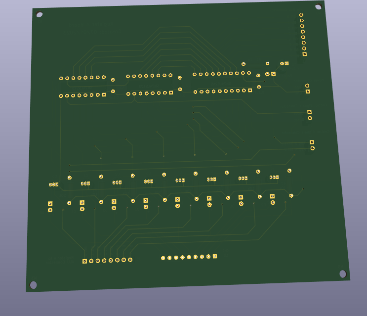
PCB 3D Viewer (Bottom)
PCB Photo (Top)
PCB Photo (Bottom)
EDIT
Image below shows the state of the board at most times regardless of what you do with inputs. They mainly flicker due to the power supply current limit being reached. Clock and reset do work but you cannot clear the register to zero and the LEDs will not go out.


