I am in the process of redesigning the electrical components of a system built around a control PCB inside a solid metal enclosure. The system is usually powered with a Class II desktop AC-DC power brick outputting 24 V 65 W on a barrel connector. (One model is the exception: it uses a Class I at 48 V with a buck converter inside the chassis.) These systems also interface with a PC via USB 2.0 (high speed / 480 Mbps).
Internally, chassis ground is connected to the power brick DC-, to all internal power supply negative terminals (two switching DC-DC converters producing 5 V and 3.3 V), to one end of the 40 W resistive heater load, to USB analog (pin 4) ground, and to USB shield. USB +5V is used only to detect the cable presence (about 130 μA constant draw). However, this setup means that the only possible connection to earth ground is via the USB shield, which doesn't seem ideal. Nor is it guaranteed -- though I expect USB shield to be connected to earth ground in a desktop computer with an ATX power supply, it's probably not connected through a laptop.
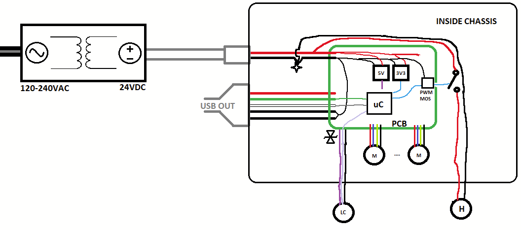
Here is a diagram of the system as it's currently being built:
M for motors, H for a heater, and LC for the analog load cell + amplifier system. Power brick is 2 wires, presumably isolated + rectified SMPS to 24 V. It's the SDI65-24-UD-P6, datasheet here.
Note that the external power supply is isolated; the only path to earth ground may or may not be connected through the USB shield.
Some considerations that may also be worth noting:
- It's a mixed-signal system with analog load cells connected through shielded cables, which are also mounted to the metal chassis. Should I be worried about ground loops? Load cells are about 30 cm - 50 cm away from the control board and the signal from the load cell realistically cannot exceed 10 Hz.
- There are lots of inductive loads and multi-amp devices in this system and voltage spikes have caused problems in previous revisions.
- Some connections lead to external components and user-accessible ports. I'm not overly familiar with transient voltage suppression on signal or power pins, and so far I just have lots of TVS diodes, one for each conductor in each connector. They're closely coupled to a solid ground plane (and thence to chassis) but if chassis is floating, what happens?
- These machines have given me some wicked static shocks, particularly in winter.
- It's going to have to pass EMC testing, which I've never been through before.
Though it's an LVDC system and doesn't require a UL/CE certification, it's going to have to pass EMC testing and in any case be relatively noise immune for the sake of the analog components.
I've heard so much conflicting advice about this topic. Should I:
- leave the system floating, or give it a solid connection to earth ground? If so, how is this usually done in metal-enclosure systems with two-conductor barrel jack power? Do Class I AC-DC desktop bricks normally connect DC- to mains earth ground? If instead DC- is left floating, what happens to ESD when the system's connected to a laptop sitting, for example, on a metal table?
- Do, or don't connect the USB cable shield at the device end? Without a shield connection, wouldn't that that just send all transients down the USB analog ground? That seems a lot worse. Or should the shield connect through a resistor? Capacitor? If so, how do I determine the right values?

