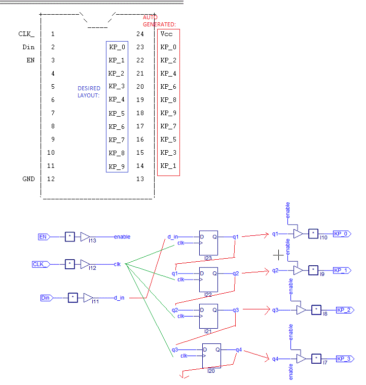
File was generated from schematic input ABEL isplever5.1:
This is a "nothing-special" Shift register (Din/CLK), and tri-state output: EN.
Output pins are Labeled (KP_0 to KP_9) should be mapped to (Q1 to Q10) and pins: (23 to 14) in order
INPUTS: CLK(1), Din(2), EN(3)

OUTPUTS: KP0(23), KP1(22), KP2(21), KP3(20), KP4(19), KP5(18), KP6(17), KP7(16), KP8(15), KP9(14)

^^^ desired sequence ^^^
However: When it autoassigns pins, it goes from PINS 23-> 14:
KP_0, KP_2, KP_4, KP_6, KP_8 (even- ascending)
KP_9, KP_7, KP_5, KP_3, KP_1 (odd - decending)
QUESTION: Can I overide the pin choices to what I need?? Can you add a preferences file it must consider?
Auto_generated Equations:
KP_0 = (q1);
KP_0.OE = (enable);

KP_1 = (q2);
KP_1.OE = (enable);

KP_2 = (q3);
KP_2.OE = (enable);

KP_3 = (q4);
KP_3.OE = (enable);

KP_4 = (q5);
KP_4.OE = (enable);

KP_5 = (q6);
KP_5.OE = (enable);

KP_6 = (q7);
KP_6.OE = (enable);

KP_7 = (q8);
KP_7.OE = (enable);

KP_8 = (q9);
KP_8.OE = (enable);

KP_9.OE = (enable);
KP_9.D = (q9);

KP_9.C = (clk);

q9.D = (q8);
q9.C = (clk);

q8.D = (q7);
q8.C = (clk);

q7.D = (q6);
q7.C = (clk);

q6.D = (q5);
q6.C = (clk);

q5.D = (q4);
q5.C = (clk);

q4.D = (q3);
q4.C = (clk);

d_in = (Din);

q3.D = (q2);
q3.C = (clk);

q2.D = (q1);
q2.C = (clk);

q1.D = (d_in);
q1.C = (clk);
clk = (CLK_);
enable = (EN);
P22V10G Programmed Logic:
-----------------------------------------
KP_9.D   = (  KP_8.Q ); " ISTYPE 'BUFFER'
KP_9.C   = (  CLK_ );
KP_9.OE  = (  EN );

KP_8.D   = (  KP_7.Q ); " ISTYPE 'BUFFER'
KP_8.C   = (  CLK_ );
KP_8.OE  = (  EN );

KP_7.D   = (  KP_6.Q ); " ISTYPE 'BUFFER'
KP_7.C   = (  CLK_ );
KP_7.OE  = (  EN );

KP_6.D   = (  KP_5.Q ); " ISTYPE 'BUFFER'
KP_6.C   = (  CLK_ );
KP_6.OE  = (  EN );

KP_5.D   = (  KP_4.Q ); " ISTYPE 'BUFFER'
KP_5.C   = (  CLK_ );
KP_5.OE  = (  EN );
...etc...
I prefer not to have to hand edit outputs every time I generate a change. Suggestions? I have OPALjr. if that helps.
I tried shuffling I10, I9, I8, I7... etc into the order I wanted and no change. I tried moving "Q inputs" to the output blocks to try to match what it was doing to what I wanted, and no change, it just undid what I shuffled.
---- Have I solved this?? ----
\ispTOOLS5_1STRT\Projects\registerproject.TT3
I edited .TT3 in a text editor so the pins are diplaying where I want.
#$ PINS 13 Din:2 CLK_:1 EN:3 KP_9:14 KP_1:22 KP_2:21 KP_3:20 KP_4:19 KP_5:18 KP_6:17 KP_7:16 KP_8:15 KP_0:23
when I re-run the compile, it draws me a chip as I wanted. Running "Create Fuse Report", then "Chip Report", it shows me what I want to see.
I have not burned a chip to try it yet. I am wondering if it modified the JED properly?
Ok, I hand-edited the JED file, and I believe I got it correct.
I don't know how to check if the checksum was altered, but since I replaced every zero I moved, hopefully the checksum is intact.
*
QP24* QF5892* QV0* F0*
 X0*
NOTE DEVICE NAME: GAL22V10B-10LP*
NOTE Table of pin names and numbers*
NOTE PINS Din:2 CLK_:1 EN:3 KP_0:23 KP_1:22 KP_2:21 KP_3:20*
NOTE PINS KP_4:19 KP_5:18 KP_6:17 KP_7:16 KP_8:15 KP_9:14*
L0044 11111111011111111111111111111111111111111111*
L0088 11110111111111111111111111111111111111111111*
L0440 11111111011111111111111111111111111111111111*
L0484 11101111111111111111111111111111111111111111*
L0924 11111111011111111111111111111111111111111111*
L0968 11111110111111111111111111111111111111111111*
L1496 11111111011111111111111111111111111111111111*
L1540 11111111111011111111111111111111111111111111*
L2156 11111111011111111111111111111111111111111111*
L2200 11111111111111101111111111111111111111111111*
L2904 11111111011111111111111111111111111111111111*
L2948 11111111111111111110111111111111111111111111*
L3652 11111111011111111111111111111111111111111111*
L3696 11111111111111111111111011111111111111111111*
L4312 11111111011111111111111111111111111111111111*
L4356 11111111111111111111111111101111111111111111*
L4884 11111111011111111111111111111111111111111111*
L4928 11111111111111111111111111111110111111111111*
L5368 11111111011111111111111111111111111111111111*
L5412 11111111111111111111111111111111111011111111*
L5808 10101010101010101010*
C6B3C*
3017

```

