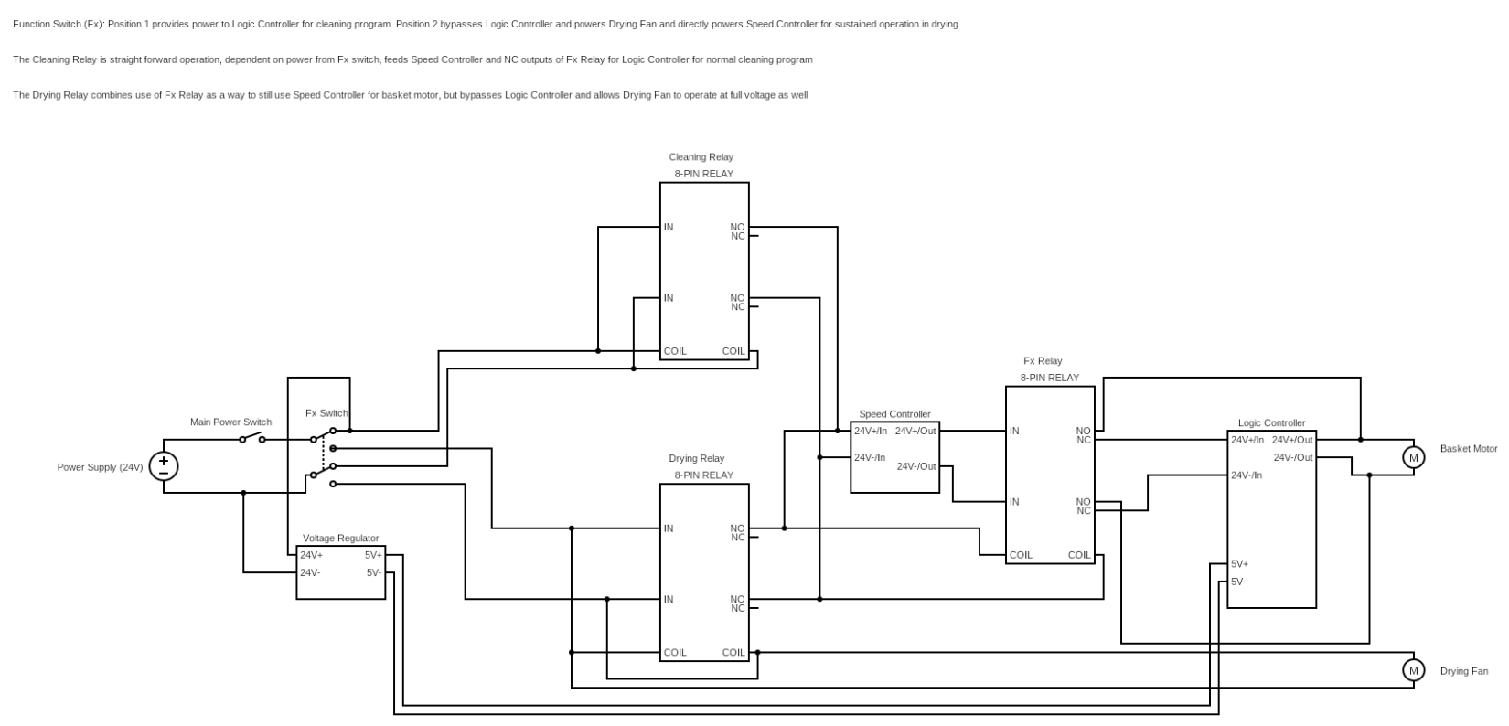
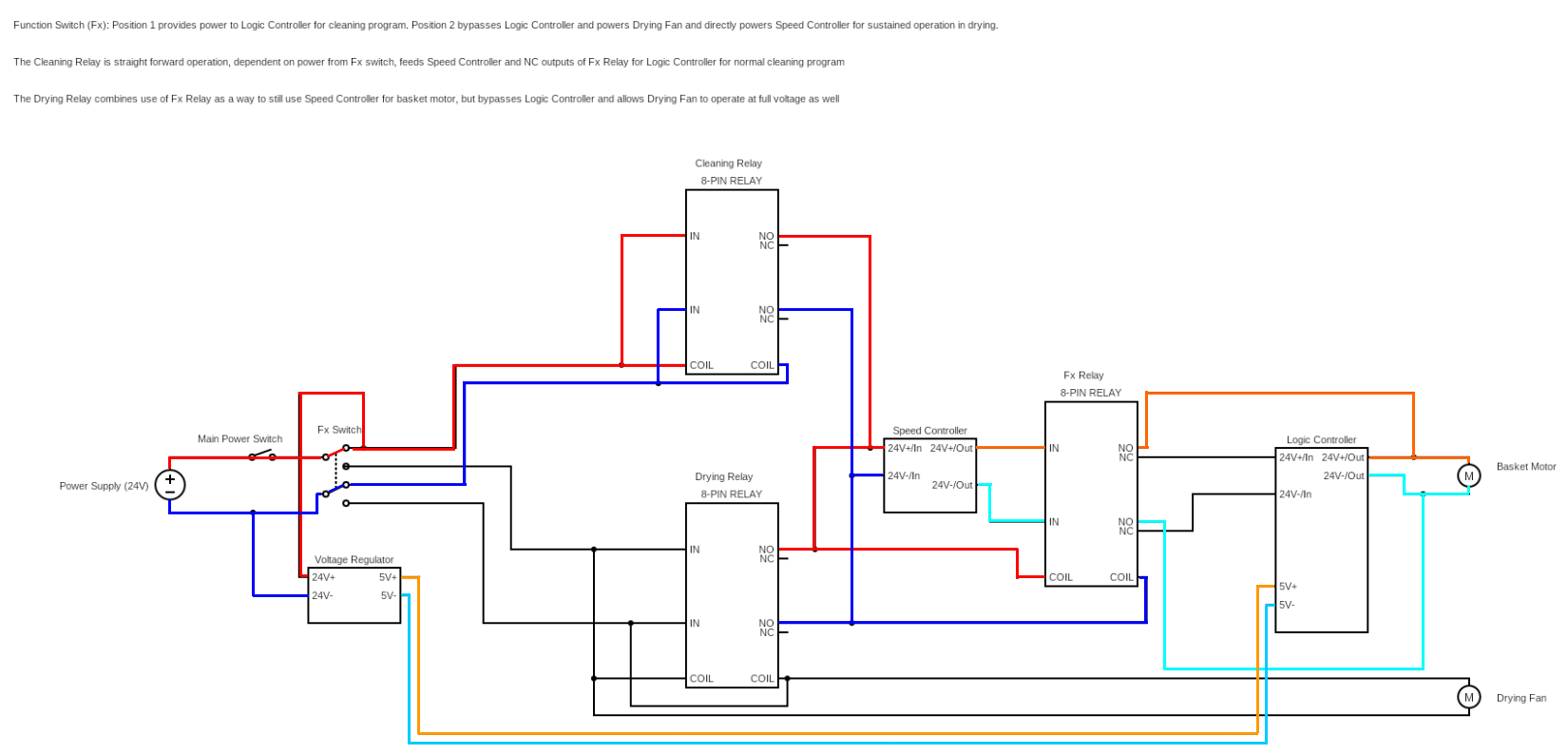
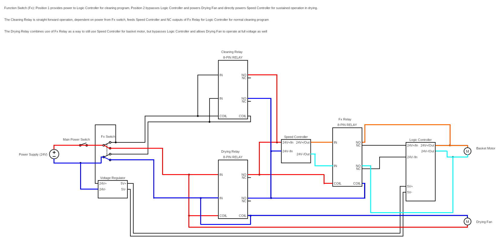
INTENDED FUNCTION: In position 1, the voltage will feed the speed controller to modulate voltage to the Logic Controller, which will serve to modulate speed of the Basket Motor from the programmed output of the Logic Controller.
Position 2 will still use the Speed Controller to modulate voltage, but will bypass the Logic Controller to indefinitely run the Basket Motor and simultaneously run the Drying Fan as well.
Much thanks for the insight in my previous question about relays. I'd like to isolate part of my circuit and get some insight into why I might be having problems. The circuit contains 3 8-pin relays, 1 voltage regulator, 1 logic controller, 1 DC speed controller, and two DC motor loads.
Within this circuit, there are 2 functions: Clean and Dry. For the time being, I want to ignore the Clean function because I recognize at least one of the problems there. So looking at the Dry function (which feeds through the currently open position of the Fx Switch and into the Drying Relay).
The problem I have is when I adjust the speed controller's built in potentiometer knob much farther beyond the lowest setting, I start getting some rhythmic clicking from my Drying and Fx Relays and my Drying Fan slows down to nearly nothing. What I'm expecting to happen is the sustained operation of the Basket Motor (with Speed Controller affecting its speed) and the full unaffected operation of the Drying Fan.
I really wanted to solve this myself, but I'm convinced now that there's a problem related to how I have things setup that is preventing expected operation of this circuit.
I wanted to add some info that will surely be asked.
Basket Motor: 24V 6.25A
Drying Fan: 24V 0.1A
Fx Switch: Rated for 250V 16A
Most wiring is 22 AWG, but some is larger. I don't believe voltage drop is an issue, all of the components are very closely located to each other, with the run of wiring being on average about 6". But I am curious about the potential need for flyback diodes. All 3 of my relays are in close proximity of each other, but I know virtually nothing about this. I'll be reading up on this, but if anyone else suspects this to be a potential issue, I'd love to hear about it.

Response for GodJihyo's answer:
I agree with you. After some consideration, the only relay I actually need is the Fx relay. I'll expand on some functionality so that context can be applied where you currently have assumptions.
The Logic Controller is a ready-made circuit board that controls a DC motor (via programming inputs) to determine amount of time to drive a motor forward, time to stop, and time to reverse the motor.
With the Cleaning and Drying relays removed from the circuit, in position 2, I would expect the Fx Switch to energize the coil of the Fx Relay and bypass the Logic Controller for uninterrupted powering of the Basket Motor. Position 1 would allow for the NC outputs of the Fx Relay to feed into the Logic Controller and allow the program to run and operate the Basket Motor as intended.
I will redesign the circuit and come back with an update. Thank you for your input. I'm a mere hobbyist, so I have much to learn.
UPDATE 1:
I've actually come full circle to realizing why I initially had the relays in place from the start. It is because the path from the Fx switch needs to go to the input of the Speed Controller in both positions. Without a relay to manage the voltage via the NO contacts, there's no way to separate the voltage based on the Fx switch. For example, here's what I've got so far before I realized the problem:
So no matter which position the Fx switch is in, the Fx Relay will have its coil energized. Now I'm sure there's a solution to this that doesn't involve 2 more relays like I originally had, but this is why they were there originally. Very eager to hear further input on this.


