0
\$\begingroup\$

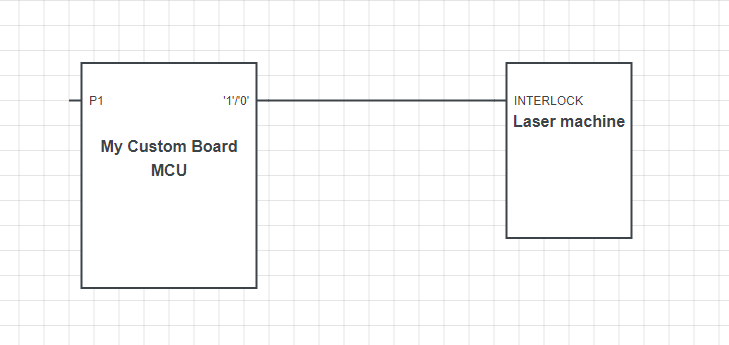
From my custom board with an MCU I need to connect to an Interlock Pin of another circuit. I have a lot of options, but I don't know what is better.

  1. Using an optocoupler, but I'm afraid the output will be shorted (the transistor is shorted) and I can't prevent it from working.

  2. Using a load switch - but I'm afraid that if the ON/OFF will get stuck to ON and the interlock will get a constant voltage on the output.

Despite all the options I have put up, I can't find a way to prevent the output from getting stuck in a fixed state. If it is 0 it worries me less, but I am afraid of a fixed 1.

EDIT: ADD SCHEMATIC -Safety way to ensure that output doesn't stuck at '1' enter image description here

\$\endgroup\$
8
  • 2
    \$\begingroup\$ too vague to be possible to answer. Please describe the circuit you are trying to control, preferably with a schematic showing its most important features. \$\endgroup\$
    – danmcb
    Commented Feb 8, 2023 at 9:01
  • 2
    \$\begingroup\$ "I'm afraid it will be shorted": So, you need to make your circuit safe against malicious manipulation? That's a very different problem, and would require talking about the complete system in much more detail, describe your attack scenario and how long and with which probability your system needs to inhibit such activity. \$\endgroup\$ Commented Feb 8, 2023 at 9:12
  • \$\begingroup\$ Needs more information. Still, you tagged this "medical", so: For a medical device, if you feel that its controller has a failure mode that prevents you from switching off the device, and not being able to switch the device off is in any way dangerous, you will have to implement an emergency hardware switch on the device itself that is guaranteed to switch the device off in a way that doesn't harm anyone connected to it, or near it. \$\endgroup\$
    – ocrdu
    Commented Feb 8, 2023 at 9:17
  • \$\begingroup\$ A watch dog timer listening to a PWM signal? \$\endgroup\$
    – winny
    Commented Feb 8, 2023 at 9:20
  • \$\begingroup\$ I can't use mechanical switch and wait that human will push it, I need to turn if off within 10mS \$\endgroup\$
    – Knowledge
    Commented Feb 8, 2023 at 9:20

2 Answers 2

0
\$\begingroup\$

The standard way is to require multiple failures rather than a single failure to put you into an unsafe condition. This is called redundancy.

The simplest way to do this with optocouplers is to use two separate outputs in series, so they both have to be on to create a '1' condition at the dangerous machine. The machine input needs a pulldown, or preferably two in parallel (so either can fail open), to maintain the input at '0' when power is off or the control cable is disconnected.

How you drive the optos depends on what you trust. If your software and MCU are impeccable, then you could drive both with one output. If you don't trust the MCU fully, then you could duplicate your MCU, use one to drive one opto and the other to drive the other.

This is assuming that you are trying to protect against some defect or random influence shorting the output device in the optocoupler. If you are worried about a malicious person tampering with the wires from your switch, then you need a whole different level of protection.

How far you go with the duplication and diversification is up to you. For instance, a package with two optos in it would satisfy output transistor duplication, but not package duplication, which would need two singly packaged optos. Some people would suggest not using the same make of opto, or the even the same technology, and make one of them a digital isolator, or a mechanical relay. In order to protect from a threat, you need to be very clear about exactly what it is and where it's coming from, and how much improvement you want in the likelyhood of no system failure.
\$\endgroup\$
1
  • \$\begingroup\$ Optocouplers are by their nature quite untrustworthy components. Since this seems to be an on/off function, a digital isolator might be more rugged. Or combining multiple different technologies, which is one way to create redundancy. For example, maybe some manner of photocoupler can be used for the purpose of determining if the laser is on or off? \$\endgroup\$
    – Lundin
    Commented Feb 8, 2023 at 10:27
0
\$\begingroup\$

Creating safety-critical equipment is difficult, especially if the equipment contains a processor. As others have said, some redundancy is essential, so that a single failure can't result in a dangerous outcome. However, you only show a single wire between the two systems, which is clearly a single point of failure, so I'd say it is impossible for your system to be safe.

If your unit is processor-based, then you have the additional complication of processor code; this can be safety-audited, but there is no guarantee that, under failure conditions, the processor is actually executing your code, rather than some random data it has jumped to after a crash.

I have experience of a unit that was pronounced 'safe' due to its code being audited, with a watchdog that would trip in the event of a failure. I had my doubts about this, so put the unit on a test rig that injected small amounts of burst-interference on the external supply lines, and the unit went crazy, executing random bits of code but not triggering the watchdog.

So the only practical solution for you is to formally declare that your unit is not suitable for use in a safety-critical application.

\$\endgroup\$

Your Answer

By clicking “Post Your Answer”, you agree to our terms of service and acknowledge you have read our privacy policy.

Not the answer you're looking for? Browse other questions tagged or ask your own question.