GPIO pins do not look like relays to arbitrary signals found on random pushbuttons. In fact that is a sure way to damage things if assumed that they can be just randomly connected together.
What you need to know how a typical reset or power button in a PC works. One wire might be ground, and the other wire may be the signal that needs to be grounded to activate an action. The pushbutton shorts the wires together to trigger the action.
Now, even with that assumption, you don't know which wire is which. You also don't know what is the idle voltage on the signal wire when it is not grounded. It might be 5V which might fry your GPIO pin which can't tolerate 5V. You also don't know how much current will flow when the signal is grounded. It might be few milliamps, or like I once encountered, tens of milliamps, which can't again fry your GPIO pin if you tried to drive it.
So that's why a relay is used as an interface between two circuits.
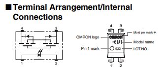
GPIO pins can be used to control a component such as a relay (electromechanical or solid state like in this case) which can then be used to replace a pushbutton.
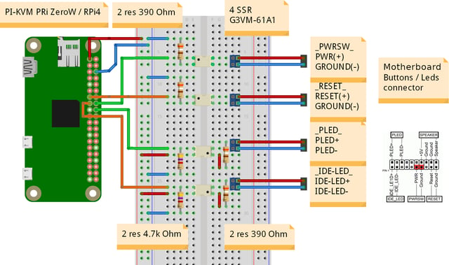
Unfortunately you only have a list of parts, but no information how the parts are connected. Like parts for a house but without blueprints you don't know how to build it or how the parts are used. There is no information why 4 relays is needed and what functions they control and in which direction.
Safe to say that GPIO is used to control the solid state relay, which can then be used in place of physical push button.
The solid state relay can basically replace a LED so current limiting resistor is needed.
Assuming the 390 ohm resistors are used for current limiting, it can likely work fine with 3.3V and 5V.
No idea for what the 4k7 resistors are for, but they may be pull-ups.


