1
\$\begingroup\$

I purchased a hot plate/magnetic stirrer from Amazon (Model SH-2, a very common cheap device from what I've found) and would like to alter the circuit so that the minimum temperature from it is lower than what I'm currently getting, which is about 55C. I'd like to get it down to 40C or so (~104F) if possible.

I opened the device up and the circuit is pretty simple. There's a DC voltage regulator for the stirrer (LM317), and a DIAC/TRIAC dimmer circuit for the heating element. I'm new to the whole DIAC/TRIAC combination (not sure how I've missed it in my hobby work, I guess not really dealing with AC is probably the reason,) so I'm not clear what specifications of each give the final output.

I believe I have created a proper schematic from the board in this device: enter image description here
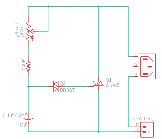
You can see the DIAC is a DB3, which has a breakdown voltage 28V-36V (I couldn't find any reference to the "ST" suffix, so that may alter the voltage range.) The TRIAC is a BTA08. The current is then controlled by the 500k POT.

In putting a meter on the output to the heating element, the minimum voltage when this turns on is around 45-50V.

My question is what could I change in this circuit to control the minimum temperature of the heating element? I presume if I could get the initial output voltage to be less than the 45-50V, that would do the trick, but I'm not clear how to get there.

\$\endgroup\$
2
  • \$\begingroup\$ What is your mains voltage? \$\endgroup\$ Commented Feb 18, 2023 at 17:50
  • \$\begingroup\$ Mains is 110vac \$\endgroup\$
    – LarryBud
    Commented Feb 18, 2023 at 18:23

1 Answer 1

1
\$\begingroup\$

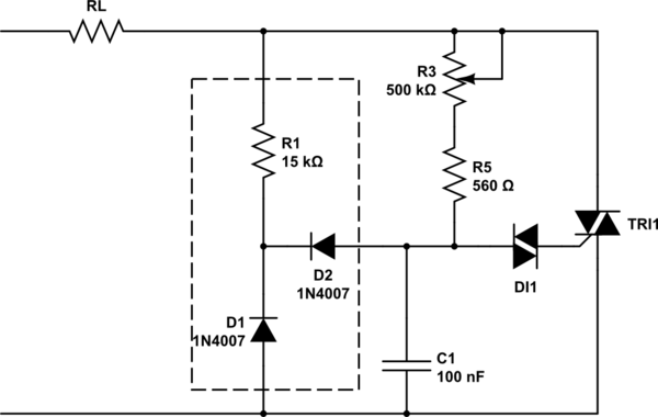
You can try a circuit to reset the capacitor voltage.

schematic

simulate this circuit – Schematic created using CircuitLab

R1 should be rated at at least 1/2 W.

\$\endgroup\$
4
  • \$\begingroup\$ Can you educate me a bit on the operation/theory here, and how you came up with the 15k resistor value? Thanks. \$\endgroup\$
    – LarryBud
    Commented Feb 18, 2023 at 20:47
  • 1
    \$\begingroup\$ This circuit is straight out of the 1972 GE Thyristor handbook. It works by discharging the capacitor through the resistor near the zero crossings (the resistor value is a trade-off between reset time and resistor power dissipation). It only resets one one polarity, and that's a big help to reduce "snap-on" but many years ago I tested a version that was the obvious bipolar extension before using a more sophisticated circuit. \$\endgroup\$ Commented Feb 18, 2023 at 20:51
  • \$\begingroup\$ Can you tell me what page you found that on? \$\endgroup\$
    – LarryBud
    Commented Feb 18, 2023 at 23:38
  • \$\begingroup\$ Page 188 of my paper copy. \$\endgroup\$ Commented Feb 19, 2023 at 1:45

Your Answer

By clicking “Post Your Answer”, you agree to our terms of service and acknowledge you have read our privacy policy.

Not the answer you're looking for? Browse other questions tagged or ask your own question.