1
\$\begingroup\$

I have a TV bed with a lift in the footboard. The lift is operated by an IR remote to a soundbar (also in the footboard). There's a couple of niggles with how it operates, such as the soundbar needing to be powered on for around 12 seconds before the TV will lift up or down. I'm currently in a bit of a drive to make everything smart, I've got Home Assistant set up with a bunch of scenes and automations and I'm currently researching ESPHome and thought it might be a good first project to get into, but I'm a bit out of my depth even after researching similar devices with an up/down action (garage doors, recliner chairs).

I have an ESP8266 NodeMCU (v3) board and I've been able to program and connect to it using ESPHome and Home Assistant. I'm not sure of the next steps now, and need a bit of help.

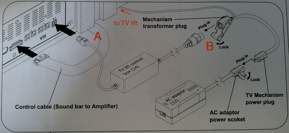
Here's a diagram of the TV lift control mechanism:

TV lift diagram

A is a 4-pin molex connector with 3 wires in it. B is a 5-pin locking din connector with 4 pins in use. It appears 2 wires go to the lift and 2 wires come from the AC adaptor, whose output is 29V at 2A to 29V at 4A max.

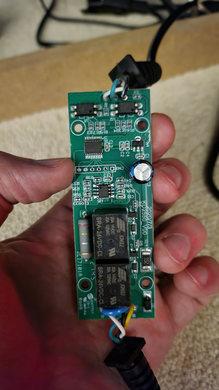
Inside the control box, there are 2 20A relays, I assume (correct me if I'm wrong) one is to make the lift go up and the other is to make the lift go down. The following photo shows the circuit board components, the top cable goes to the soundbar for control and the bottom cable goes to the AC adaptor and lift mechanism.

circuit board

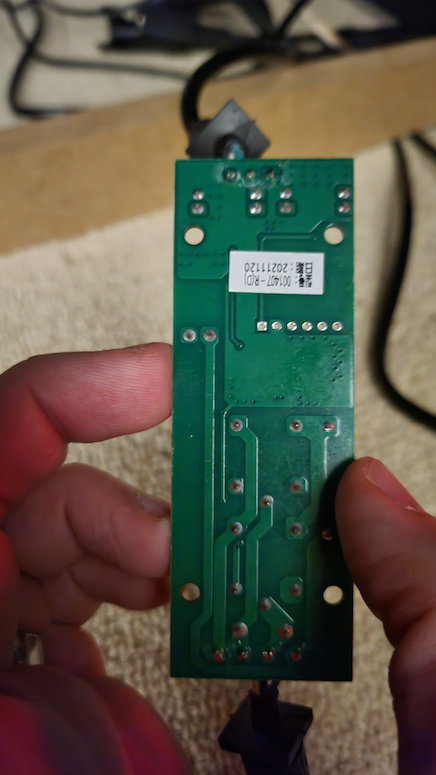
Here's the rear of the board (not sure how helpful it is but I wanted to be thorough):

circuit board rear

So, I think I have two options for my ESP8266 board:

  1. replicate the behaviour of the 3 wires coming from the soundbar; or
  2. control 2 identical relays to send power to the lift

I think 1 would be simpler, but I'm not entirely sure. How can I figure out what those wires do using a multimeter, then set up my ESP8266 to do the same? And how can I ensure the control box remains powered by my device when the soundbar is switched off?

\$\endgroup\$
4
  • \$\begingroup\$ there are 2 20A relays, I assume (correct me if I'm wrong) one is to make the lift go up and the other is to make the lift go down ... how can anyone correct you? ... you have to determine that yourself or supply a schematic diagram \$\endgroup\$
    – jsotola
    Commented Feb 26, 2023 at 19:29
  • 2
    \$\begingroup\$ Caution !!! ... do not assume that the board is safe to handle when powered on ... the power supply output may not be isolated from AC power ... powerline voltage may exist between the board and earth ground \$\endgroup\$
    – jsotola
    Commented Feb 26, 2023 at 19:32
  • 2
    \$\begingroup\$ That control board has a whole lot more on it that just the 2 relays. If I had to guess I'd say there's probably some current-sense mechanism so that the control board can detect when the lift motor hits its limits and stops trying to raise or lower the TV. If you were to try to build your own relay circuit you'd need to also do something similar. \$\endgroup\$
    – brhans
    Commented Feb 26, 2023 at 19:33
  • 2
    \$\begingroup\$ Brhans is right, there's a 0.24Ω resistor associated with the contacts and what looks like some analog circuitry. That may be a safety to prevent injury (as in electric garage door openers) and there may be mechanical limit switches in addition. \$\endgroup\$ Commented Feb 26, 2023 at 19:38

1 Answer 1

2
\$\begingroup\$

Option 1 is probably the safest bet - relying on the existing board which has already been designed to do everything required to interface with hardware.

I would assume the two components at the top of the board as shown (4-pin DIP packages) are optocouplers. In which case interfacing the existing board with a different device (such as ESP) will be a case of figuring out what the signals. No extra hardware is likely required to interface the ESP, just hook up to two IO pins.

The three wires feeding in will be two control signals (white and black) and GND (green). I would try probing them with a multi-meter when the TV is moving up and down. If they are just on-off control signals a voltage meter should be sufficient to figure out what they do. If they are something more complex, you'd probably want a logic analyser.

In a simple world the signals would be just "Go-up" and "Go-down", but they could be something more complicated.

\$\endgroup\$
2
  • \$\begingroup\$ Thank you, this is what I was hoping. I'll take a look with the multimeter when I get the chance. \$\endgroup\$
    – Andy E
    Commented Feb 27, 2023 at 12:44
  • 1
    \$\begingroup\$ You were absolutely correct, green was GND, white was "up" and black was "down". The voltage was 3.3V too, so it was extremely simple to make a simple program for ESPHome with an "up" button and a "down" button and connect the wires. I'm going to buy a few of those connectors and finish the job properly with my own little box that sits between the control box and the soundbar connection. Thanks again for your answer! \$\endgroup\$
    – Andy E
    Commented Feb 27, 2023 at 16:25

Your Answer

By clicking “Post Your Answer”, you agree to our terms of service and acknowledge you have read our privacy policy.

Not the answer you're looking for? Browse other questions tagged or ask your own question.