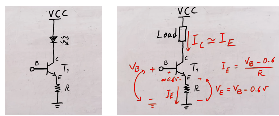
The circuit you show works as shown, and it draws roughly the LED current the formulas imply. But it wastes potentially quite a lot energy unnecessarily.
To convert PWM into a roughly constant current, use an inductor in series with the load, and a second switch - eg. a diode - to keep the inductor conducting at all times. The PWM frequency scales the current ripple amplitude when the inductance is held constant: the higher the frequency, the lower the ripple. For a fixed PWM frequency, the larger the inductor, the smaller the ripple.
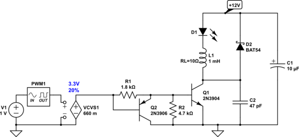
A minimally wasteful PWM LED driver circuit would look as follows:

simulate this circuit – Schematic created using CircuitLab
Q1 is a saturating switch. Q2 desaturates Q1 on turn-off, and improves performance when the duty cycles are small.
The current loop D1-L1-D2 should be kept small. C2 limits Q2's dV/dt and dI/dt on turn-on, and should be connected directly between the collector and emitter.
R1 and R2 are chosen to keep Q1 saturated, while consuming a reasonable current from the PWM GPIO pin.
The average LED current, given a PWM duty cycle between 0 (0%) and 1 (100%), is:
$$ I_{avg} = D.\!C. \frac{V^+ - V_{Df}}{R_L},$$
where \$V_{Df}\$ is the LED forward voltage - usually 1.5-2V, and \$R_L\$ is the DC resistance of the inductor. The inductor resistance is a trade-off between the reasonable duty cycle and losses.
A small 1mH inductor in a through-hole package that resembles a resistor would have about 10Ω series resistance.
For the 20% example, the average current would be a bit below 200mA.


