4
\$\begingroup\$

So I'm trying to implement a constant current source to conduct a specific measurement using a AD8276 differential amplifier. I'm trying got derive the equations my self for sanity check, and to give a little me weight when I present my idea. This is what I have work out but my math doesn't checkout, here is a [circuit diagram][2] for my calculations
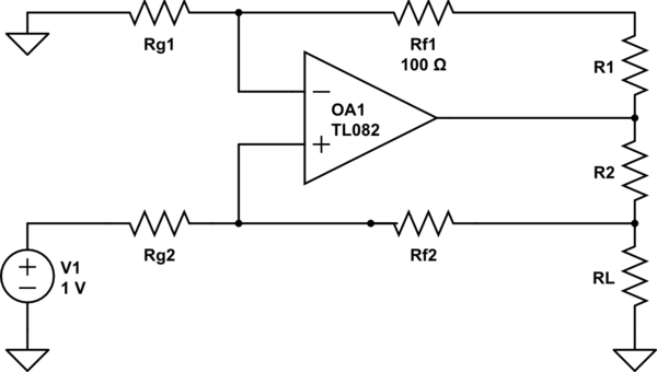
schematic

simulate this circuit – Schematic created using CircuitLab

things to know Rf1=Rf2=Rg1=Rg2 and R1=R2

The equivalent resistance of the parallel circuit consisting of the load resistance and the negative feedback lines $$R_{eq} = {({R_L}^{-1}+(R_1+R_2+R_{f1}+R_{g1})^{-1}})^{-1} $$

The voltage at the positive terminal, using the voltage divider. This is mainly where I thin I have gone wrong. $$V_1 = V_{ref} * ({R_{f2}+R_{eq}})/({R_{g2}+R_{f2}+R_{eq}}) $$

Next it is understood that the negative terminal of the op amp will have the same voltage as the positive terminal, 0 potential diffrence $$V_1 = V_2$$

V2 will be propped completely across Vg1 and therefore the current through R1,R2 and Rf1 can be calculated by calculating the current through Rg1 $$I_{Rg1} = V_2 /R_{g1} $$

The total current supplied by Vref is $$I_{total} = (V_{ref} - V_1)/R_{g2} $$

And therefore the current through the load is $$I_L =I_{total} - I_{g1} $$

This does not give me the same results as the equation provided from the sources of www.analog.com/library/analogDialogue/archives/43-09/current_source.html figure 5 without the transitor. $$I_o = I_L = V_{ref}((1/40K)+(1/R_2) $$

Any thoughts?

EDIT: I fixed my diagram error

\$\endgroup\$
1
  • 2
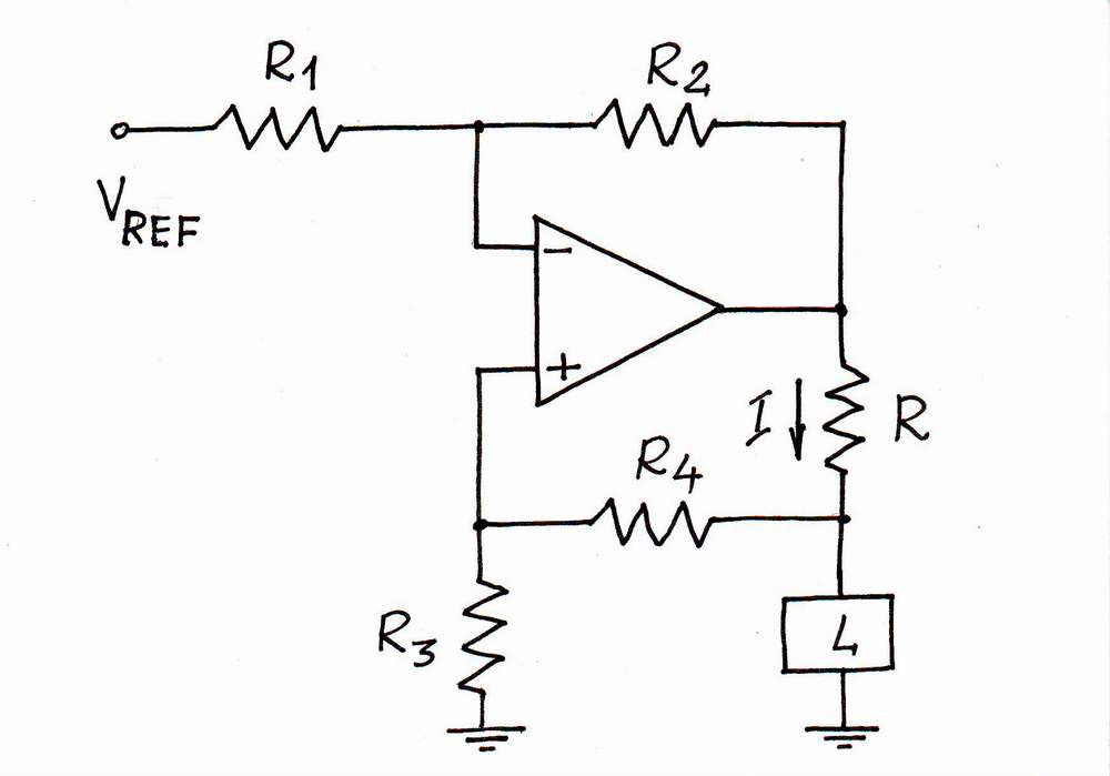
    \$\begingroup\$ Analog's circuit is different. The op-amp is "upside down" compared to your diagram. Plus other details, like the transistor, and the other op-amp doing the sensing feedback. In that circuit, the current across \$R_l\$ has no other path to go by out across \$R_{load}\$. (Since the + input on the AD8603 op-amp in the feedback has a high impedance) So if the circuit regulates the voltage drop across \$R_l\$, it thereby programs the current across the load. \$\endgroup\$
    – Kaz
    Commented Apr 16, 2013 at 1:20

1 Answer 1

1
\$\begingroup\$

You've made a basic error - you have the inverted and non-inverted inputs of your op-amp swapped. Here's what it should look like: -

enter image description here

Here's a good document on it. Alternatively look in the data sheet for the AD8276 - page 17 top right-hand corner shows a constant current generator using an extra transistor and I suspect your design was based on this circuit but without the extra grunt from the transistor.

(This text is here to satisfy SO's 6 character edit requirement...)

\$\endgroup\$
3
  • \$\begingroup\$ You're correct I'm trying to recreate the circuit from the data sheet on page 17. I'll give the article a read thanks for the material, do you have any thought on the math I have provided? \$\endgroup\$
    – Lpaulson
    Commented Apr 16, 2013 at 15:13
  • \$\begingroup\$ You need to develop the math from the correct circuit then it's easy (well, easier)!! \$\endgroup\$
    – Andy aka
    Commented Apr 16, 2013 at 15:21
  • \$\begingroup\$ Sorry, I should have mentioned I revised the circuit. \$\endgroup\$
    – Lpaulson
    Commented Apr 16, 2013 at 16:18

Your Answer

By clicking “Post Your Answer”, you agree to our terms of service and acknowledge you have read our privacy policy.

Not the answer you're looking for? Browse other questions tagged or ask your own question.